Dodge Dakota (R1). Manual - part 782


  Index      Dodge     Dodge Dakota (R1) - service repair manual 2000 year


Search            


Content   ..  780  781  782  783   ..


Dodge Dakota (R1). Manual - part 782


QUARTER TRIM PANEL

REMOVAL

(1) Remove door sill cover as necessary to clear

quarter trim.

(2) Remove cab back panel trim.
(3) Remove front and rear shoulder belt turning

loops.

(4) Remove the screws attaching the quarter trim

panel to the cab back panel.

(5) Grasp quarter trim panel and firmly pull out-

ward to disengage the push-in fasteners.

(6) Route front and rear shoulder belts through

access slots in quarter trim panel.

(7) Separate club cab quarter trim panel from

quarter panel (Fig. 15).

INSTALLATION

(1) Position trim panel in vehicle.
(2) Route belt webbing through access slots in

quarter trim panel.

(3) Position quarter trim panel on quarter panel

and engage hooks at base of quarter trim panel.

(4) Press

quarter

trim

panel

inward

to

seat

push-in fasteners.

(5) Install screws attaching quarter trim panel to

cab back panel.

(6) Install cab back panel trim.
(7) Install door sill cover as necessary.
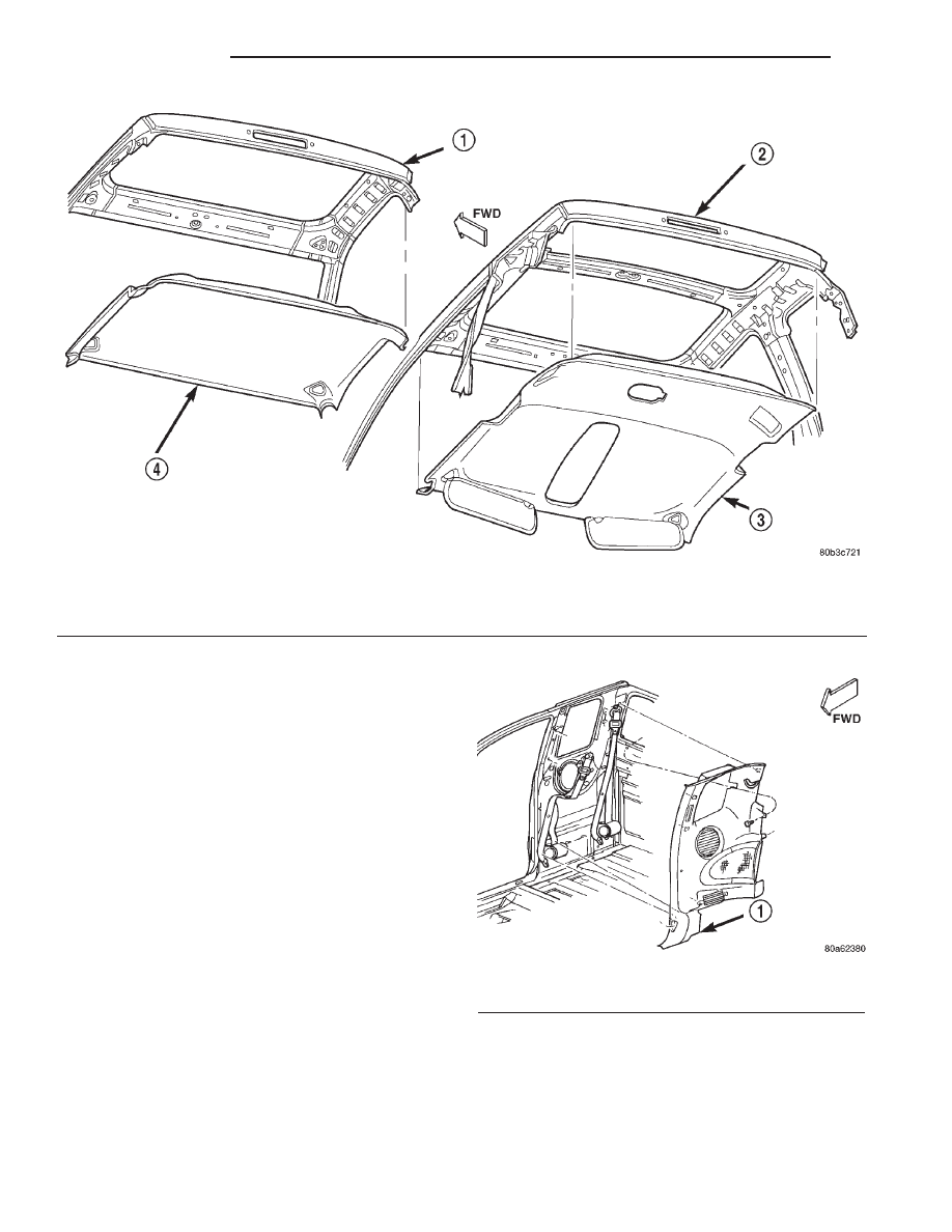
Fig. 14 Headliner

1 - STANDARD CAB
2 - EXTENDED CAB

3 - HEADLINER
4 - HEADLINER

Fig. 15 Quarter Trim Panel

1 - QUARTER TRIM PANEL

23 - 116

INTERIOR

AN

HEADLINER (Continued)

REAR CAB BACK PANEL TRIM

REMOVAL

The rear cab back panel trim is attached to the cab

with push-in fasteners.

(1) Grasp rear cab back panel trim and firmly pull

to release from cab (Fig. 16) and (Fig. 17).

INSTALLATION

(1) Position rear cab back panel trim on cab, align

holes and press into place.

REAR STORAGE BOX

REMOVAL

(1) Lift rear seat.
(2) Remove bolts attaching storage box to floor pan

(Fig. 18).

(3) Remove rear seat belt/buckle anchor bolts.
(4) Route rear seat belt/buckle through slots in

rear of storage box.

(5) Separate storage box from vehicle.

INSTALLATION

(1) Position storage box in vehicle.
(2) Route rear seat belt/buckle through slots in

rear of storage box.

(3) Install rear seat belt/buckle anchor bolts.
(4) Install bolts attaching storage box to floor pan.
(5) Lower seat.

Fig. 16 Rear Cab Back Panel Trim

1 - REAR SEAT BACK
2 - REAR CAB PANEL TRIM

Fig. 17 Rear Cab Back Panel Trim With Carpet

1 - CAB BACK PANEL CARPET

Fig. 18 Storage Box

1 - JACK STORAGE POUCH
2 - STORAGE BOX

AN

INTERIOR

23 - 117

REAR VIEW MIRROR

REMOVAL

(1) Loosen the mirror base setscrew (Fig. 19).
(2) Slide the mirror base upward and off the

bracket.

INSTALLATION

(1) Position the mirror base at the bracket and

slide it downward onto the support bracket.

(2) Tighten setscrew to1 N·m (9 in. lbs.) torque.

SHIFT BEZEL

REMOVAL

(1) Remove shift boot/s.
(2) Lift bin cup holder and remove bolts attaching

shift bezel to floor pan (Fig. 20).

(3) Remove screw under shift boot attaching patch

plate to floor pan.

(4) Disengage 4WD shift indicator lamp connector,

if equipped (Fig. 21) and (Fig. 22).

(5) Separate shift bezel from vehicle.

INSTALLATION

(1) Position shift bezel in vehicle.
(2) Engage 4WD shift indicator lamp connector, if

equipped.

(3) Install screw under shift boot attaching patch

plate to floor pan.

(4) Install bolts in cup holder attaching shift bezel

to floor pan.

(5) Install shift boot/s.

Fig. 19 Rearview Mirror

1 - MIRROR
2 - SUPPORT BUTTON

Fig. 20 Shift Bezel 4x2

1 - SHIFT BEZEL CUP HOLDER
2 - SHIFT BEZEL 4 x 2
3 - PATCH PLATE

Fig. 21 Shift Bezel 4X4 Manual Trans

1 - SHIFT BEZEL CUP HOLDER
2 - SHIFT BEZEL 4 x 4
3 - PATCH PLATE

23 - 118

INTERIOR

AN

SUN VISORS

REMOVAL

NOTE: All vehicles with driver and passenger side
airbags must have a colored-coded, 5-bullet point
airbag warning label applied to the sunvisor face
surface (in the stored position). When replacing the
sunvisor, verify label availability and ensure the
label is installed.

(1) Remove the screws that attach the sunvisor

arm support bracket to the headliner and the roof
panel (Fig. 23).

(2) Detach the sunvisor from the visor supports.
(3) Remove the sunvisor from the headliner and

roof panel.

(4) If necessary, remove the screw attaching the

visor supports to the headliner and roof panel.

INSTALLATION

NOTE: All vehicles with driver and passenger side
airbags must have a colored-coded, 5-bullet point
airbag warning label applied to the sunvisor face
surface (in the stored position). When replacing the
sunvisor, verify label availability and ensure the
label is installed.

(1) If removed, install the visor supports.
(2) Position the sunvisor in the visor supports and

align the arm support bracket holes with the head-
liner holes.

(3) Install the screws that attach the sunvisor arm

support bracket to the headliner and the roof panel.

REAR VIEW MIRROR SUPPORT
BRACKET

INSTALLATION

(1) Mark the position for the mirror bracket on the

outside of the windshield glass with a wax pencil.

(2) Clean the bracket contact area on the glass.

Use a mild powdered cleanser on a cloth saturated
with isopropyl (rubbing) alcohol. Finally, clean the
glass with a paper towel dampened with alcohol.

(3) Sand the surface on the support bracket with

fine grit-sandpaper. Wipe the bracket surface clean
with a paper towel.

(4) Apply accelerator to the surface on the bracket

according to the following instructions:

• Crush the vial to saturate the felt applicator.

• Remove the paper sleeve.

• Apply accelerator to the contact surface on the

bracket.

Fig. 22 Shift Bezel 4X4 Automatic Trans

1 - SHIFT BEZEL CUP HOLDER
2 - SHIFT BEZEL 4 x 4

Fig. 23 Sunvisors

1 - VISOR SUPPORT
2 - SUNVISOR

AN

INTERIOR

23 - 119

SHIFT BEZEL (Continued)


Content   ..  780  781  782  783   ..