Dodge Dakota (R1). Manual - part 749


  Index      Dodge     Dodge Dakota (R1) - service repair manual 2000 year


Search            


Content   ..  747  748  749  750   ..


Dodge Dakota (R1). Manual - part 749


(4) With Bearing Splitter P-334 positioned under

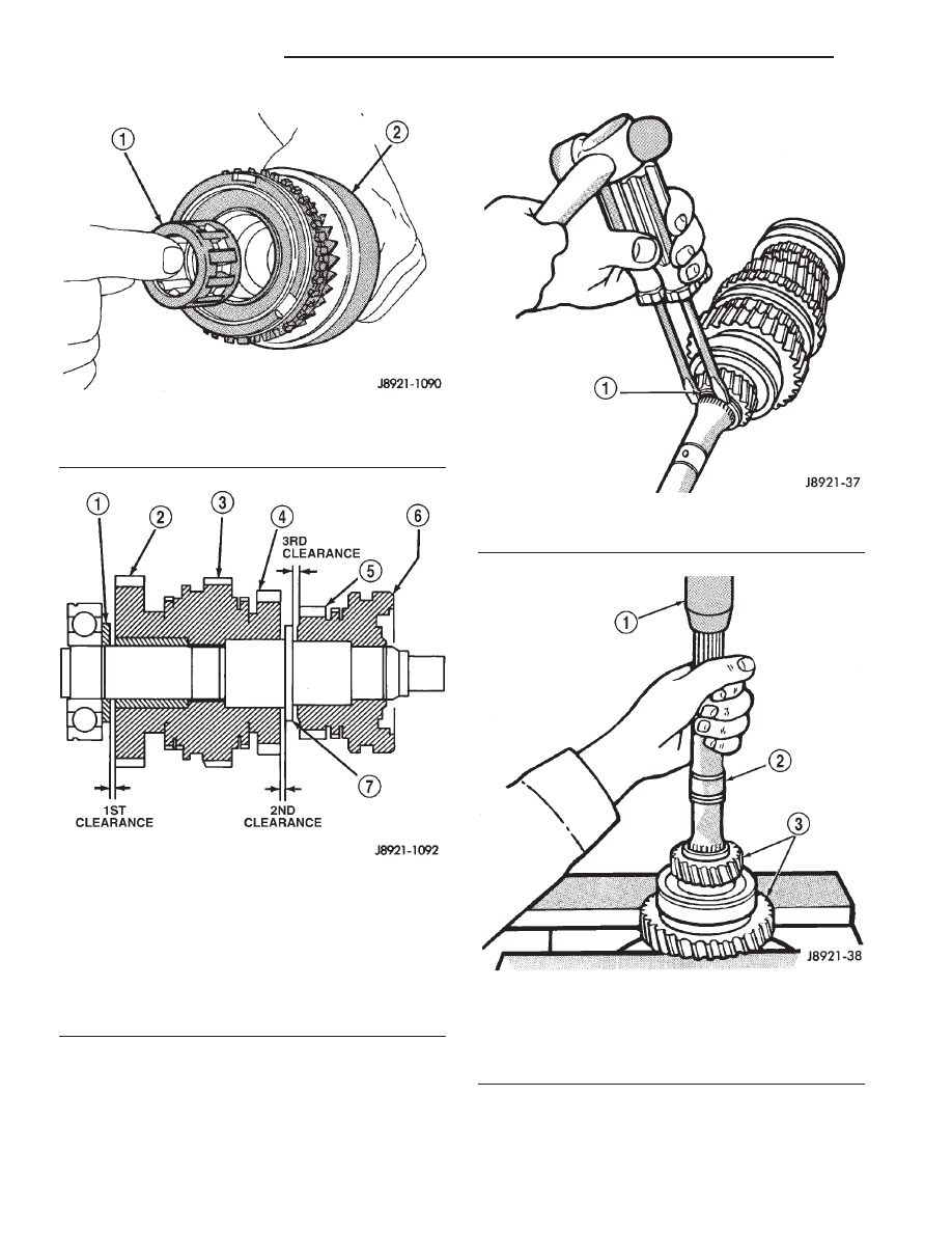
first gear, press fifth gear, rear bearing, first gear,
and first gear thrust washer off output shaft (Fig.
114).

Fig. 111 OUTPUT SHAFT PILOT BEARING

1 - OUTPUT SHAFT PILOT BEARING
2 - INPUT SHAFT ASSEMBLY

Fig. 112 OUTPUT SHAFT GEAR THRUST

CLEARANCE

1 - THRUST WASHER
2 - FIRST GEAR
3 - REVERSE GEAR AND HUB
4 - SECOND GEAR
5 - THIRD GEAR
6 - 3–4 SYNCHRO SLEEVE AND HUB
7 - OUTPUT SHAFT FLANGE

Fig. 113 FIFTH GEAR SNAP-RING

1 - SNAP RING

Fig. 114 FIFTH GEAR, FIRST GEAR BEARING AND

THRUST WASHER

1 - PRESS RAM
2 - OUTPUT SHAFT
3 - FIRST-FIFTH GEAR-BEARING ASSEMBLY

21a - 38

MANUAL - AX15

R1

OUTPUT SHAFT (Continued)

(5) Remove first gear thrust washer locating pin

from output shaft.

(6) Remove first gear needle roller bearing from

output shaft.

(7) Remove first gear spacer from output shaft.
(8) Remove first gear synchronizer ring.
(9) Remove select fit snap-ring holding the 1-2 syn-

chronizer/reverse gear onto the output shaft.

(10) With Bearing Splitter P-334 positioned under

second gear, press 1-2 synchronizer/reverse gear and
second gear from output shaft (Fig. 115).

(11) Remove second gear needle roller bearing

from the output shaft or second gear.

(12) Remove select fit snap-ring holding the 3-4

synchronizer onto the output shaft (Fig. 116).

(13) Using Bearing Splitter P-334 or suitable press

plates positioned under third gear, press the 3–4 syn-
chronizer and third gear from output shaft (Fig. 117).

(14) Remove third gear needle roller bearing from

output shaft or gear.

Fig. 115 SECOND GEAR, REVERSE GEAR AND 1-2

SYNCHRONIZER/REVERSE GEAR

1 - PRESS RAM
2 - SECOND GEAR
3 - 1-2 SYNCHRONIZER HUB

Fig. 116 3-4 SYNCHRONIZER SNAP RING

1 - 3-4 SYNCHRONIZER SNAP RING

Fig. 117 3-4 SYNCHRONIZER AND THIRD GEAR

1 - 3-4 SYNCHRONIZER
2 - THIRD GEAR

R1

MANUAL - AX15

21a - 39

OUTPUT SHAFT (Continued)

ASSEMBLY

(1) Lubricate transmission components with speci-

fied gear lubricant during assembly.

(2) If necessary, assemble 1-2 and 3-4 synchronizer

hubs, sleeves, springs and key inserts (Fig. 118).

(3) Install third gear needle bearing onto the out-

put shaft.

(4) Install third gear over bearing and onto output

shaft flange.

(5) Install third gear synchronizer ring to third

gear.

(6) Position the 3-4 synchronizer onto the output

shaft.

(7) With Adapter 6761 and a shop press, press the

3-4 synchronizer onto the output shaft.

(8) Select thickest snap-ring that will fit into the

snap-ring groove of the output shaft (Fig. 119).

(9) Install snap-ring to hold 3-4 synchronizer onto

output shaft.

(10) Verify third gear thrust clearance with feeler

gauge (Fig. 120). Clearance should be 0.10-0.30 mm
(0.003-0.0118 in.). If clearance is out of specification,
refer to Cleaning and Inspection section within this
group.

(11) Install second gear needle bearing onto output

shaft.

(12) Install second gear over bearing and onto out-

put shaft flange.

(13) Install second gear synchronizer ring onto sec-

ond gear.

Fig. 118 SYNCHRONIZER IDENTIFICATION

1 - 3-4 SLEEVE AND HUB
2 - REVERSE GEAR AND 1-2 SLEEVE AND HUB

Fig. 119 SELECT 3-4 SYNCHRONIZER SNAP-RIN

I.D. MARK

SNAP RING

THICKNESS

MM (IN.)

A

1.80 - 1.85

(0.0709 - 0.0728)

B

1.85 - 1.90

(0.0728 - 0.0748)

C

1.90 - 1.95

(0.0748 - 0.0768)

D

1.95 - 2.00

(0.0768 - 0.0787)

E

2.00 - 2.05

(0.0787 - 0.0807)

F

2.05 - 2.10

(0.0807 - 0.0827)

G

2.10 - 2.15

(0.0827 - 0.0846)

Fig. 120 THIRD GEAR CLEARANCE

1 - FEELER GAUGE
2 - THIRD GEAR

21a - 40

MANUAL - AX15

R1

OUTPUT SHAFT (Continued)

(14) Position 1-2 synchronizer/reverse gear assem-

bly onto splines of output shaft.

(15) With Installer MD-998805, Adapter 6761, and

a shop press, press the 1-2 synchronizer/reverse gear
onto the output shaft.

(16) Select thickest snap-ring that will fit into the

snap-ring groove of the output shaft (Fig. 121).

I.D.

MARK

SNAP RING

THICKNESS

MM (IN.)

B

2.35 - 2.40

(0.0925 - 0.0945)

C

2.40 - 2.45

(0.0945 - 0.0965)

D

2.45 - 2.50

(0.0965 - 0.0984)

E

2.50 - 2.55

(0.0984 - 0.1004)

F

2.55 - 2.60

(0.1004 - 0.1024)

G

2.60 - 2.65

(0.1024 - 0.1043)

(17) Install snap-ring to hold 1-2 synchronizer/re-

verse gear onto output shaft.

(18) Install first gear synchronizer ring into 1-2

synchronizer/reverse gear.

(19) Install first gear spacer onto the input shaft

and against the 1-2 synchronizer/reverse gear snap-
ring.

(20) Install first gear needle bearing onto output

shaft (Fig. 122).

(21) Install first gear onto output shaft and over

bearing.

(22) Install first gear thrust washer locating pin

into the output shaft.

(23) Install first gear thrust washer onto the out-

put shaft. Rotate thrust washer until the washer
locating pin aligns with the notch in the washer.

(24) Position output shaft rear bearing onto output

shaft with snap ring groove in bearing outer race
toward rear of output shaft.

(25) Install

bearing

onto

output

shaft

with

Installer L-4507 and hammer.

(26) Install snap-ring onto output shaft rear bear-

ing outer race.

Fig. 121 SECOND GEAR AND SYNCHRONIZER

ASSEMBLY

1 - SECOND GEAR
2 - REVERSE GEAR AND 1-2 SLEEVE
3 - FIRST/REVERSE HUB
4 - SELECT FIT SNAP RING
5 - INSERTS AND SPRINGS
6 - SYNCHRO RING
7 - NEEDLE BEARING

Fig. 122 FIRST AND FIFTH GEAR COMPONENTS

1 - SYNCHRO RING
2 - SPACER
3 - PIN
4 - BEARING
5 - FIFTH GEAR
6 - THRUST WASHER
7 - NEEDLE BEARING
8 - FIRST GEAR

R1

MANUAL - AX15

21a - 41

OUTPUT SHAFT (Continued)


Content   ..  747  748  749  750   ..