Dodge Dakota (R1). Manual - part 748
BEARING RETAINER
REMOVAL
(1) Remove release bearing and lever from the
transmission.
(2) Remove front bearing retainer bolts from the
transmission case.
(3) Remove front bearing retainer.
(4) Remove front bearing retainer seal with a suit-
able pry tool.
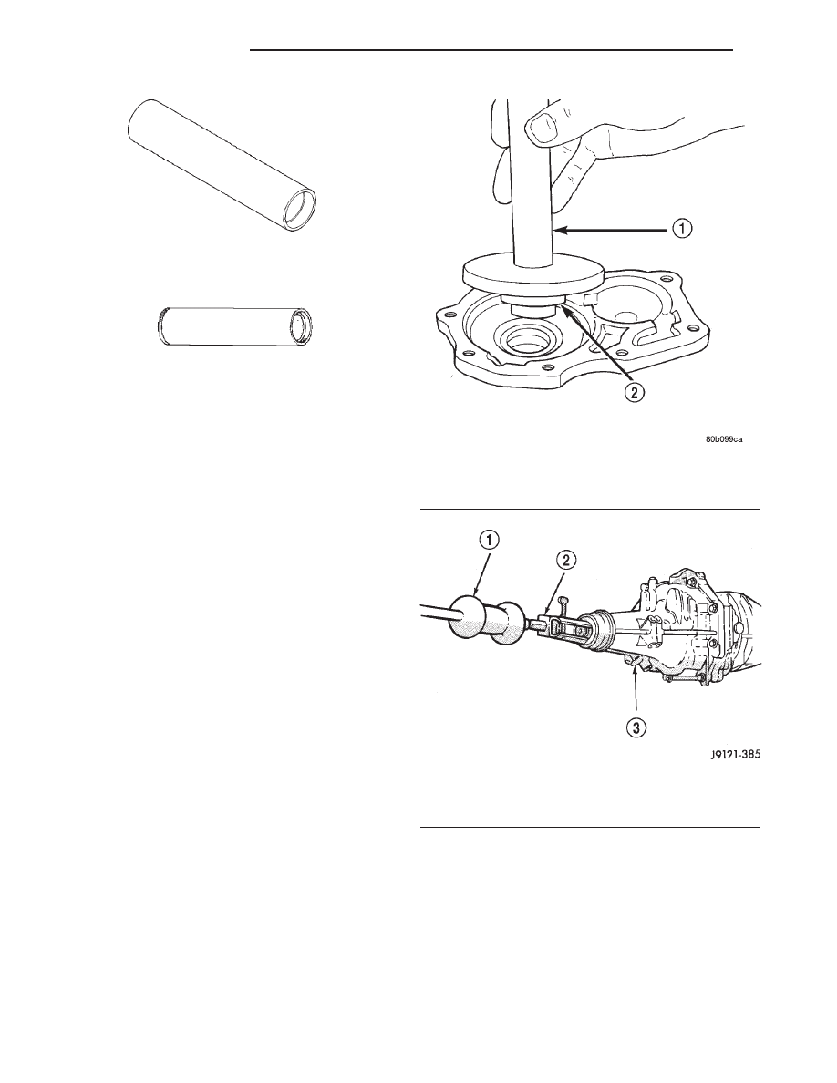
INSTALLATION
(1) Install new front bearing retainer seal with
Handle C-4171 and Installer 8209 (Fig. 102).
(2) Remove any residual gasket material from the
sealing surfaces of the bearing retainer and the
transmission case.
(3) Install new front bearing retainer gasket to
the front bearing retainer.
(4) Install front bearing retainer and tighten the
bolts to 17 N·m (12 ft. lbs.).
(5) Install release bearing and lever onto the
transmission.
EXTENSION HOUSING SEAL
REMOVAL
(1) Raise and support vehicle.
(2) Remove propeller shaft.
(3) Remove extension housing seal with a slide
hammer and puller (Fig. 103).
INSTALLATION
(1) Clean seal bore of extension housing of any
residual sealer material from original seal.
(2) Install new extension housing seal with Han-
dle C-4171 and Installer 8212 (Fig. 104). The seal is
located 0 ± 0.5 mm (0 ± 0.02 in.) to the face of the
extension housing
(3) Install propeller shaft.
(4) Check and add fluid to transmission as neces-
sary.
(5) Lower vehicle.
INSTALLER MD998805
INSTALLER L-4507
Fig. 102 BEARING RETAINER SEAL
1 - HANDLE
2 - INSTALLER
Fig. 103 EXTENSION HOUSING SEAL
1 - SLIDE HAMMER
2 - PULLER
21a - 34
MANUAL - AX15
R1
MANUAL - AX15 (Continued)