Dodge Dakota (R1). Manual - part 740


  Index      Dodge     Dodge Dakota (R1) - service repair manual 2000 year


Search            


Content   ..  738  739  740  741   ..


Dodge Dakota (R1). Manual - part 740


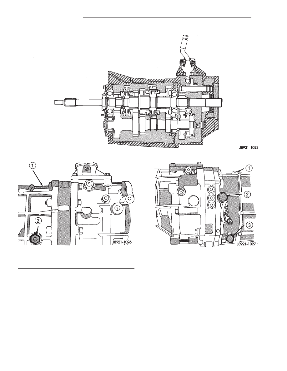
Fig. 1 AX15 Manual Transmission

Fig. 2 Fill Plug Location

1 - TRANSMISSION CASE
2 - FILL PLUG

Fig. 3 Drain Plug Location

1 - TRANSMISSION CASE
2 - BACKUP LIGHT SWITCH
3 - DRAIN PLUG

21a - 2

MANUAL - AX15

R1

MANUAL - AX15 (Continued)

Gear ratios for the transmission are as follows:
• First gear: 3.83:1

• Second gear: 2.33:1

• Third gear: 1.44:1

• Fourth gear: 1.00:1

• Fifth gear: 0.79:1

• Reverse: 4.22:1

DIAGNOSIS AND TESTING - MANUAL
TRANSMISSION

• Verify correct lubricant level.

• Check lubricant for overheated or improper

fluid.

• Verify proper operation of the clutch assembly.

• If problem persists it will be necessary to

remove the transmission from the vehicle and per-
form one or more of the repair procedures called out
in this group of the service manual.

LOW LUBRICANT LEVEL

A low transmission lubricant level is generally the

result of a leak, inadequate lubricant fill or an incor-
rect lubricant level check.

Leaks can occur at the mating surfaces of the gear

case, intermediate plate and adaptor or extension
housing, or from the front/rear seals. A suspected
leak could also be the result of an overfill condition.

Leaks at the rear of the extension or adapter hous-

ing will be from the housing oil seals. Leaks at com-
ponent mating surfaces will probably be the result of
inadequate sealer, gaps in the sealer, incorrect bolt
tightening, or use of a non-recommended sealer.

A leak at the front of the transmission will be from

either the front bearing retainer or retainer seal.
Lubricant may be seen dripping from the clutch
housing after extended operation. If the leak is
severe, it may also contaminate the clutch disc caus-
ing the disc to slip, grab, and/or chatter.

A correct lubricant level check can only be made

when the vehicle is level. Also allow the lubricant to
settle for a minute or so before checking. These rec-
ommendations will ensure an accurate check and
avoid an underfill or overfill condition. Always check
the lubricant level after any addition of fluid to avoid
an incorrect lubricant level condition.

HARD SHIFTING

Hard shifting is usually caused by a low lubricant

level, improper, or contaminated lubricants. The con-
sequence of using non–recommended lubricants is
noise, excessive wear, internal bind, and hard shift-
ing. Substantial lubricant leaks can result in gear,
shift rail, synchro, and bearing damage. If a leak
goes undetected for an extended period, the first indi-
cations of component damage are usually hard shift-
ing and noise.

Component damage, incorrect clutch adjustment,

or a damaged clutch pressure plate or disc are addi-
tional probable causes of increased shift effort. Incor-
rect adjustment or a worn/damaged pressure plate or
disc can cause incorrect release. If the clutch problem
is advanced, gear clash during shifts can result.
Worn or damaged synchro rings can cause gear clash
when shifting into any forward gear. In some new or
rebuilt transmissions, new synchro rings may tend to
stick slightly causing hard or noisy shifts. In most
cases, this condition will decline as the rings wear–
in.

TRANSMISSION NOISE

Most manual transmissions make some noise dur-

ing normal operation. Rotating gears generate a mild
whine that is audible, but generally only at extreme
speeds.

Severe, highly audible transmission noise is gener-

ally the initial indicator of a lubricant problem.
Insufficient, improper, or contaminated lubricant will
promote rapid wear of gears, synchros, shift rails,
forks and bearings. The overheating caused by a
lubricant problem, can also lead to gear breakage.

REMOVAL

(1) Disconnect the negative battery cable.

Fig. 4 Upper Radiator Support

1 - UPPER RADIATOR SUPPORT RETAINING BOLTS
2 - FRONT CLOSURE PANEL
3 - UPPER FAN SHROUD RETAINING BOLTS
4 - UPPER RADIATOR HOSE

R1

MANUAL - AX15

21a - 3

MANUAL - AX15 (Continued)

(2) Remove the (2) upper fan shroud retaining

bolts (Fig. 4).

(3) Raise the vehicle on the hoist.
(4) Remove the (2) lower fan shroud retaining

bolts.

(5) Remove the transmission oil drain plug and

drain the transmission fluid. Reinstall the plug to
contain residue fluid.

NOTE: Mark the propeller shaft position in relation
to the rear axle companion flange. The propeller
shaft must be installed in the same position it was
in before removal.

(6) Remove the (4) universal joint clamp retaining

bolts from the rear axle pinion. Remove the propeller
shaft from the rear axle companion flange and tape
the universal joint bearing caps in place.

CAUTION: Wrap the universal joint bearing caps in
place with tape to prevent the bearing caps from
falling off.

(7) Remove the (4) center propeller shaft bearing

retaining nuts and remove the propeller shaft assem-
bly from the vehicle.

(8) Remove the (2) exhaust system inlet pipe

retaining nuts.

(9) Remove the exhaust system support bracket

bolt from the clutch housing.

(10) Remove the exhaust system support bracket

nut from the transmission support crossmember (Fig.
5).

(11) Remove the (2) clutch slave cylinder retaining

nuts (Fig. 6). Remove the slave cylinder by pulling it
straight off of the mounting studs.

(12) Remove the (4) transmission mount retaining

nuts from the transmission crossmember (Fig. 5).

(13) Position a transmission jack and raise the

transmission assembly enough to allow the cross-
member to be slide straight back.

(14) Remove the fuel line support bracket retain-

ing bolt from the transmission support crossmember.

(15) Remove the transmission support crossmem-

ber retaining bolts. Slide the crossmember as far
rearward as possible.

(16) Lower the transmission assembly enough to

access the shifter retaining bolts.

(17) Remove the (4) shifter retaining bolts (Fig. 7).

Fig. 5 Transmission Support Crossmember

1 - EXHAUST SYSTEM SUPPORT BRACKET RETAINING NUT
2 - CROSSMEMBER
3 - TRANSMISSION
4 - TRANSMISSION MOUNT RETAINING NUTS

Fig. 6 Clutch Slave Cylinder

1 - SLAVE CYLINDER RETAINING NUTS
2 - HYDRAULIC CLUTCH SLAVE CYLINDER
3 - TRANSMISSION
4 - FLUID SUPPLY LINE

21a - 4

MANUAL - AX15

R1

MANUAL - AX15 (Continued)

(18) Remove the (2) misfire sensor retaining bolts

from the clutch housing.

(19) Be sure all wiring is disconnected from the

transmission assembly.

(20) Secure the transmission to the transmission

jack with safety chains.

(21) Remove the clutch housing retaining bolts.

Pull the transmission straight back until the input
shaft clears the clutch assembly. Remove the trans-
mission from the vehicle.

DISASSEMBLY

ADAPTER/EXTENSION HOUSING

(1) Drain transmission lubricant, if necessary.
(2) Remove release bearing and lever.
(3) Remove clutch housing bolts and remove hous-

ing (Fig. 8).

(4) Remove bolts holding shift tower to transmis-

sion case.

(5) Remove shift tower from transmission case

(Fig. 9).

(6) Remove shift tower gasket from shift tower or

transmission case (Fig. 10).

Fig. 7 Shifter Assembly Retaining Bolts

1 - SHIFTER ASSEMBLY RETAINING BOLTS
2 - TRANSMISSION

Fig. 8 CLUTCH HOUSING

1 - HOUSING -TO- TRANSMISSION BOLTS
2 - CLUTCH HOUSING
3 - TRANSMISSION

Fig. 9 SHIFT TOWER

1 - SHIFT TOWER
2 - ADAPTER/EXTENSION HOUSING

R1

MANUAL - AX15

21a - 5

MANUAL - AX15 (Continued)


Content   ..  738  739  740  741   ..