Dodge Dakota (R1). Manual - part 733


  Index      Dodge     Dodge Dakota (R1) - service repair manual 2000 year


Search            


Content   ..  731  732  733  734   ..


Dodge Dakota (R1). Manual - part 733


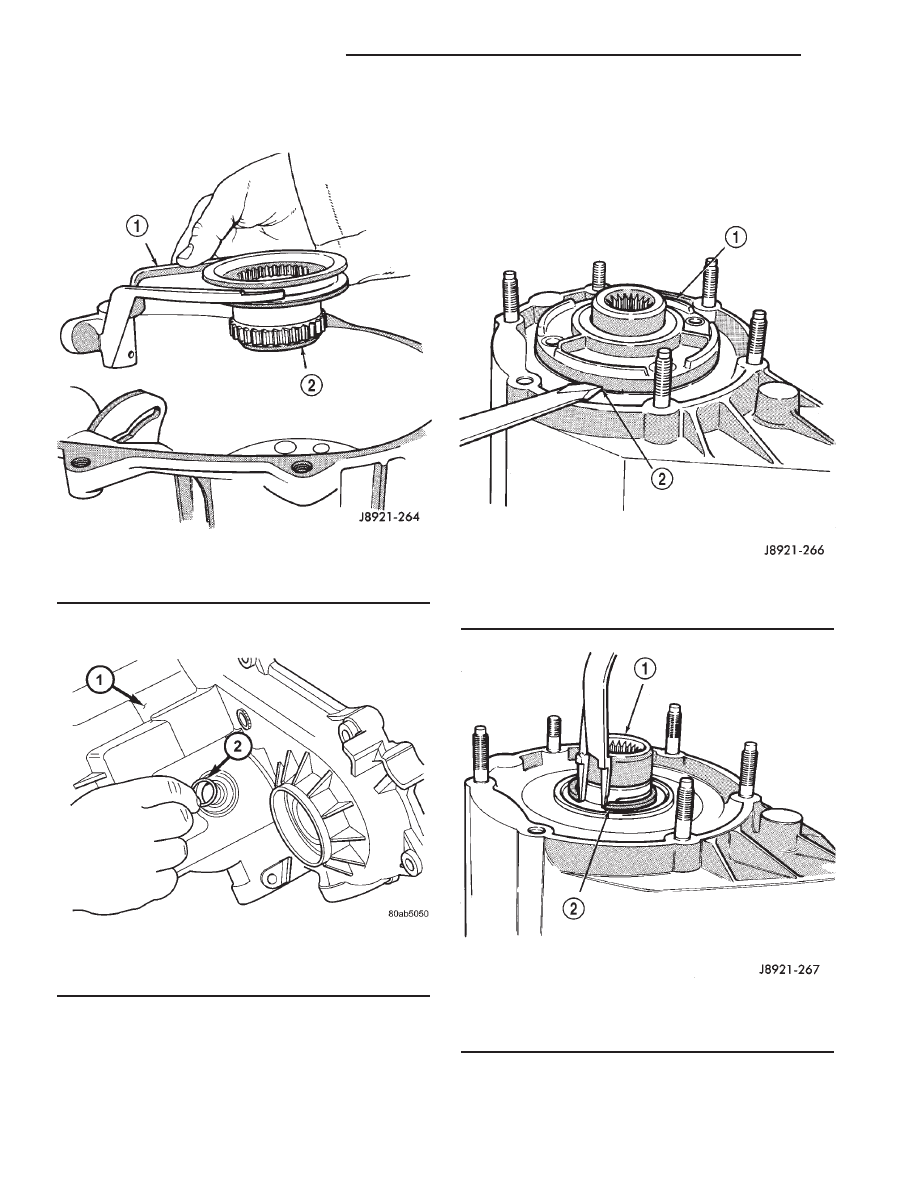
(12) Remove low range fork and hub (Fig. 25).
(13) Remove shift sector.

(14) Remove shift sector o-ring (Fig. 26).

INPUT GEAR/LOW RANGE ASSEMBLY

(1) Remove front bearing retainer bolts.
(2) Remove front bearing retainer. Carefully pry

retainer loose with screwdriver (Fig. 27). Position
screwdriver in slots cast into retainer.

(3) Remove input gear snap-ring (Fig. 28).

Fig. 25 Low Range Fork And Hub Removal

1 - LOW RANGE FORK
2 - FORK HUB

Fig. 26 Remove the Shift Sector O-Ring

1 - TRANSFER CASE FRONT HOUSING
2 - SHIFT SECTOR O-RING

Fig. 27 Front Bearing Retainer Removal

1 - FRONT BEARING RETAINER
2 - RETAINER SLOT

Fig. 28 Remove the Input Gear Snap-Ring

1 - INPUT GEAR
2 - SNAP-RING

21 - 576

TRANSFER CASE - NV244

AN

TRANSFER CASE - NV244 (Continued)

(4) Remove input/low range gear assembly from

bearing with Tool Handle C-4171 and Tool 7829-A
(Fig. 29).

(5) Remove low range gear snap-ring (Fig. 30).
(6) Remove input gear retainer, thrust washers,

and input gear from low range gear (Fig. 31).

(7) Inspect low range annulus gear (Fig. 32). Gear

is not a serviceable component. If damaged,
replace gear and front case as an assembly.

Fig. 29 Input And Low Range Gear Assembly

Removal

1 - INPUT-LOW RANGE GEARS
2 - SPECIAL TOOL 7829-A
3 - SPECIAL TOOL C-4171

Fig. 30 Remove the Low Range Gear Snap-Ring

1 - LOW RANGE GEAR SNAP-RING

Fig. 31 Low Range And Input Gear Assembly

1 - THRUST WASHERS
2 - LOW RANGE GEAR
3 - INPUT GEAR
4 - RETAINER

Fig. 32 Inspecting Low Range Annulus Gear

1 - LOW RANGE ANNULUS GEAR

AN

TRANSFER CASE - NV244

21 - 577

TRANSFER CASE - NV244 (Continued)

(8) Remove oil seals from the following compo-

nents:

• front bearing retainer.

• rear retainer.

• oil pump.

• case halves.

DIFFERENTIAL

(1) Mark differential case halves for reference.
(2) Remove differential case bolts.
(3) Invert differential on workbench.
(4) Separate top case from bottom case. Use slots

in case halves to pry them apart (Fig. 33).

(5) Remove thrust washers and planet gears from

case pins (Fig. 34).

(6) Remove mainshaft and sprocket gears from

bottom case (Fig. 35). Note gear position for reference
before separating them.

Fig. 33 Separating Differential Case Halves

1 - TOP CASE
2 - CASE BOLTS
3 - CASE BOLTS
4 - CASE SLOTS
5 - CASE BOLTS

Fig. 34 Planet Gears And Thrust Washer Removal

1 - BOTTOM CASE
2 - THRUST WASHERS (12)
3 - PLANET GEARS (6)

Fig. 35 Mainshaft And Sprocket Gear Removal

1 - MAINSHAFT GEAR
2 - SPROCKET GEAR
3 - BOTTOM CASE

21 - 578

TRANSFER CASE - NV244

AN

TRANSFER CASE - NV244 (Continued)

CLEANING

Clean the transfer case parts with a standard

parts cleaning solvent. Remove all traces of sealer
from the cases and retainers with a scraper and
3M™ all purpose cleaner. Use compressed air to
remove solvent residue from oil feed passages in the
case halves, retainers, gears, and shafts.

The oil pickup screen can be cleaned with solvent.

Shake excess solvent from the screen after cleaning
and allow it to air dry. Do not use compressed air.

INSPECTION

MAINSHAFT/SPROCKET/HUB INSPECTION

Inspect the splines on the hub and shaft and the

teeth on the sprocket. Minor nicks and scratches can
be smoothed with an oilstone. However, replace any
part that is damaged.

Check the contact surfaces in the sprocket bore

and on the mainshaft. Minor nicks and scratches can
be smoothed with 320-400 grit emery cloth but do not
try to salvage the shaft if nicks or wear is severe.

INPUT GEAR AND PLANETARY CARRIER

Check the teeth on the gear (Fig. 36). Minor nicks

can be dressed off with an oilstone but replace the
gear if any teeth are broken, cracked, or chipped. The
bearing surface on the gear can be smoothed with
300-400 grit emery cloth if necessary.

Examine the carrier body and pinion gears for

wear or damage. The carrier will have to be replaced
as an assembly if the body, pinion pins, or pinion
gears are damaged.

Check the lock ring and both thrust washers for

wear or cracks. Replace them if necessary. Also
replace the lock retaining ring if bent, distorted, or
broken.

Fig. 36 Input Gear And Carrier Components

1 - PLANETARY CARRIER

4 - CARRIER LOCK RING

2 - REAR THRUST WASHER

5 - CARRIER LOCK RETAINING RING

3 - FRONT THRUST WASHER

6 - INPUT GEAR

AN

TRANSFER CASE - NV244

21 - 579

TRANSFER CASE - NV244 (Continued)


Content   ..  731  732  733  734   ..