Dodge Dakota (R1). Manual - part 730


  Index      Dodge     Dodge Dakota (R1) - service repair manual 2000 year


Search            


Content   ..  728  729  730  731   ..


Dodge Dakota (R1). Manual - part 730


SELECTOR SWITCH

DESCRIPTION

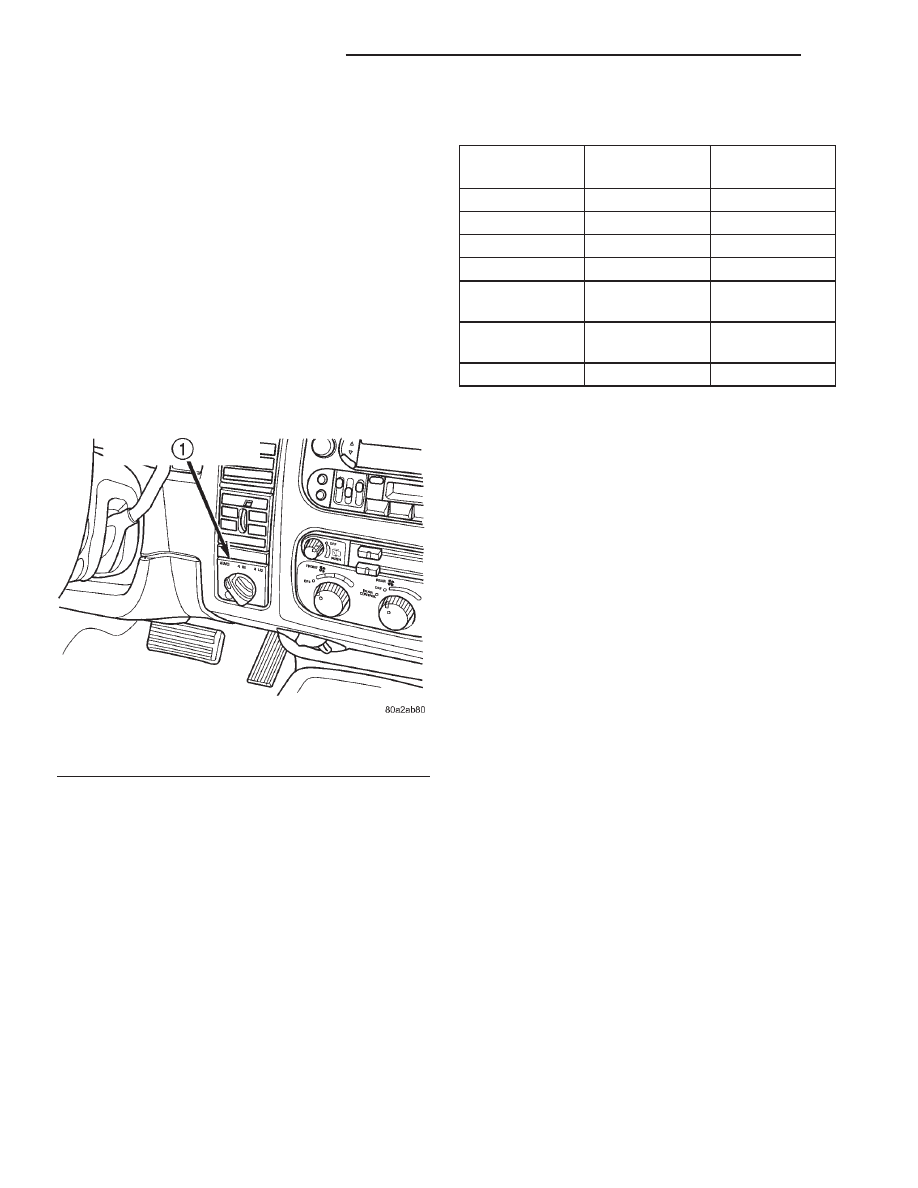
The selector switch assembly (Fig. 77) is mounted

in the vehicle Instrument Panel (IP) and consists of a
rotary knob connected to a resistive network for the
mode and range shift selections. Also located in this
assembly is a recessed, normally open momentary
switch for making shifts into and out of transfer case
NEUTRAL. A pen, or similar instrument, is used to
make a NEUTRAL shift selection, thus reducing the
likelihood of an inadvertent shift request.

The selector switch also contains four light emit-

ting diode’s (LED’s) to indicate the transfer case posi-
tion and whether a shift is in progress.

OPERATION

As the position of the selector switch varies, the

resistance between the Mode Sensor supply voltage
pin and the Mode Sensor output will vary. Hardware,
software, and calibrations within the Transfer Case
Control Module (TCCM) are provided that interpret
the selector switch resistance as given in the table
below:

SELECTOR SWITCH INTERPRETATION

Step

Resistance

Range (ohms)

Required

Interpretation

A

<200

Shorted

B

400-700

NEUTRAL

C

1050-1450

4LO

D

1850-2300

4H

E

3050-5950

2WD/AWD

(Default)

F

9.5-12.5K

In between

positions

G

>15.5K

Open

For resistances between the ranges B-E shown for

each valid position (T-Case NEUTRAL, 4LO, 4HI,
2WD/AWD), the TCCM may interpret the resistance
as:

• either of the neighboring valid positions.

• as an invalid fault position.
For resistances between the ranges E and F shown

for AWD/2WD and in-between positions, the TCCM
may interpret the resistance as:

• the AWD/2WD position.

• an invalid fault position.

• a valid in-between position.
For resistances between the ranges F and G shown

for in-between positions and fault condition (open),
the TCCM may interpret the resistance as:

• a valid in-between position.

• an invalid fault position.
For resistances between the ranges A and B shown

for the fault condition (short) and , T-Case NEU-
TRAL, the TCCM may interpret the resistance as:

• the T-Case NEUTRAL position.

• an invalid fault position.
The LED’s in the selector assembly are illuminat-

ed/flashed in the following manner to indicate a par-
ticular condition or state.

• A solidly illuminated LED indicates a success-

fully completed shift and the current operating mode
of the transfer case. While a shift has been requested
but not yet completed, the LED for the source trans-
fer case position remains solidly illuminated.

• A flashing operating mode LED for the desired

gear indicates that a shift to that position has been
requested, but all of the driver controllable conditions
have not been met. This is in an attempt to notify
the driver that the transmission needs to be put into
NEUTRAL, the vehicle speed is too great, or some
other condition outlined (other than a diagnostic fail-
ure that would prevent this shift) above is not met.
Note that this flashing will continue indefinitely
until the conditions are eventually met, or the selec-

Fig. 77 Selector Switch

1 - TRANSFER CASE MODE SELECTOR SWITCH

21 - 564

TRANSFER CASE - NV233

AN

tor switch position is changed, or if diagnostic rou-
tines no longer allow the requested shift.

• If the driver attempts to make a shift into trans-

fer case NEUTRAL, and any of the driver controlla-
ble conditions are not met, the request will be
ignored until all of the conditions are met or until
the NEUTRAL select button is released. Additionally
the neutral lamp will flash, or begin to flash while
the button is depressed and operator controllable
conditions are not being met. All of the LED’s except
the Neutral will flash if any of the operator control-
lable conditions for shifting are not met while the
Neutral button is depressed. This

9toggle9 type of fea-

ture is necessary because the TCCM would interpret
another request immediately after the shift into
transfer case NEUTRAL has completed.

• No LED’s illuminated indicate a fault in the

transfer case control system.

SHIFT MOTOR

DESCRIPTION

The shift motor (Fig. 78) consists of a permanent

magnet D.C. motor with gear reduction to convert a
high speed-low torque device into a low speed-high
torque device. The output of the device is coupled to
a shaft which internally moves the mode and range
forks that change the transfer case operating ranges.
The motor is rated at 25 amps maximum at 72° F
with 10 volts at the motor leads.

OPERATION

The transfer case shift motor responds to the

Transfer Case Control Module (TCCM) commands to
move the transfer case shift sector bi-directionally, as
required, to obtain the transfer case operating mode
indicated by the instrument panel mounted selector
switch.

REMOVAL

(1) Raise the vehicle on a suitable hoist.
(2) Remove the front propeller shaft. (Refer to 3 -

DIFFERENTIAL

&

DRIVELINE/PROPELLER

SHAFT/PROPELLER SHAFT - REMOVAL)

(3) Disengage the wiring connectors from the shift

motor and mode sensor.

(4) Remove the front output shaft companion

flange from the transfer case.

(5) Remove the bolts (Fig. 79) holding the shift

motor and mode sensor assembly onto the transfer
case.

(6) Separate the shift motor and mode sensor

assembly from the transfer case.

Fig. 78 Shift Motor - Shown Inverted

1 - TRANSFER CASE SHIFT MOTOR

Fig. 79 Remove the Shift Motor and Mode Sensor

Assembly Bolts

1 - TRANSFER CASE
2 - SHIFT MOTOR AND MODE SENSOR ASSEMBLY
3 - BOLT

AN

TRANSFER CASE - NV233

21 - 565

SELECTOR SWITCH (Continued)

INSTALLATION

(1) Verify that the shift sector o-ring is clean and

properly positioned over the shift sector and against
the transfer case.

(2) Position the shift motor and mode sensor

assembly onto the transfer case.

(3) Install the bolts (Fig. 80) to hold the assembly

onto the transfer case. Tighten the bolts to 16-24
N·m (12-18 ft.lbs.).

CAUTION: If the original shift motor and mode sen-
sor assembly bolts are reused, be sure to use
Mopar

T

Lock & Seal or Loctite™ 242 to replenish

the lock patch material originally found on the bolts

(4) Engage the wiring connectors to the shift motor

and mode sensor.

(5) Install the transfer case front output shaft

companion flange onto the transfer case. Tighten the
flange nut to 122-176 N·m (90-130 ft.lbs.).

(6) Install the front propeller shaft. (Refer to 3 -

DIFFERENTIAL

&

DRIVELINE/PROPELLER

SHAFT/PROPELLER SHAFT - INSTALLATION)

(7) Refill the transfer case as necessary.
(8) Lower vehicle and verify transfer case opera-

tion.

Fig. 80 Install the Shift Motor and Mode Sensor

Assembly Bolts

1 - TRANSFER CASE
2 - SHIFT MOTOR AND MODE SENSOR ASSEMBLY
3 - BOLT

21 - 566

TRANSFER CASE - NV233

AN

SHIFT MOTOR (Continued)

TRANSFER CASE - NV244

TABLE OF CONTENTS

page

page

TRANSFER CASE - NV244

DESCRIPTION . . . . . . . . . . . . . . . . . . . . . . . . . . 567
OPERATION. . . . . . . . . . . . . . . . . . . . . . . . . . . . 568
DIAGNOSIS AND TESTING . . . . . . . . . . . . . . . . 568

TRANSFER CASE - NV244. . . . . . . . . . . . . . . 568

REMOVAL . . . . . . . . . . . . . . . . . . . . . . . . . . . . . 569
DISASSEMBLY . . . . . . . . . . . . . . . . . . . . . . . . . . 570
CLEANING . . . . . . . . . . . . . . . . . . . . . . . . . . . . . 579
INSPECTION . . . . . . . . . . . . . . . . . . . . . . . . . . . 579
ASSEMBLY . . . . . . . . . . . . . . . . . . . . . . . . . . . . 581
INSTALLATION . . . . . . . . . . . . . . . . . . . . . . . . . . 593
SPECIFICATIONS. . . . . . . . . . . . . . . . . . . . . . . . 593
SPECIAL TOOLS . . . . . . . . . . . . . . . . . . . . . . . . 594

FLUID

STANDARD PROCEDURE . . . . . . . . . . . . . . . . . 595

FLUID DRAIN AND REFILL . . . . . . . . . . . . . . . 595

FRONT OUTPUT SHAFT SEAL

REMOVAL . . . . . . . . . . . . . . . . . . . . . . . . . . . . . 596

INSTALLATION . . . . . . . . . . . . . . . . . . . . . . . . . . 596

MODE SENSOR

DESCRIPTION . . . . . . . . . . . . . . . . . . . . . . . . . . 596
OPERATION. . . . . . . . . . . . . . . . . . . . . . . . . . . . 597

REAR RETAINER BUSHING AND SEAL

REMOVAL . . . . . . . . . . . . . . . . . . . . . . . . . . . . . 598
INSTALLATION . . . . . . . . . . . . . . . . . . . . . . . . . . 598

SELECTOR SWITCH

DESCRIPTION . . . . . . . . . . . . . . . . . . . . . . . . . . 599
OPERATION. . . . . . . . . . . . . . . . . . . . . . . . . . . . 599

SHIFT MOTOR

DESCRIPTION . . . . . . . . . . . . . . . . . . . . . . . . . . 600
OPERATION. . . . . . . . . . . . . . . . . . . . . . . . . . . . 600
REMOVAL . . . . . . . . . . . . . . . . . . . . . . . . . . . . . 600
INSTALLATION . . . . . . . . . . . . . . . . . . . . . . . . . . 601

TRANSFER CASE - NV244

DESCRIPTION

The NV244 is an electronically controlled full and

part-time transfer case with no two wheel drive oper-
ation.

A differential in the transfer case is used to control

torque transfer to the front and rear axles. A low
range gear reduction system provides increased low
speed torque capability for off road operation. The
low range provides a 2.72:1 reduction ratio.

The geartrain is mounted in two aluminum case

halves attached with bolts. The mainshaft front and
rear bearings are mounted in aluminum retainer
housings bolted to the case halves.

OPERATING RANGES

NV244 operating ranges are:
• AWD(All-Wheel Drive)

• 4HI (Part-time)

• 4LO

• NEUTRAL
The AWD mode can be used at any time and on

any road surface.

The 4HI (Part-time) and 4LO ranges are for off

road use only. The only time these ranges can be
used is when the road surface is covered with snow,
ice, or other loose slippery material.

SHIFT MECHANISM

Operating

ranges

are

selected

with

a

dash

mounted shift selector switch. The shift selector
switch provides a input to the Transfer Case Control
Module (TCCM) to indicate the driver’s desire to
change operating ranges. The TCCM uses this input,
along with the input from the transfer case mounted
mode sensor and information from the vehicle’s bus,
to determine if a shift is permitted. If the TCCM
decides the shift is permitted, the TCCM controls the
shift motor, mounted to the exterior of the transfer
case, to perform the shift.

AN

TRANSFER CASE - NV244

21 - 567


Content   ..  728  729  730  731   ..