Dodge Dakota (R1). Manual - part 702


  Index      Dodge     Dodge Dakota (R1) - service repair manual 2000 year


Search            


Content   ..  700  701  702  703   ..


Dodge Dakota (R1). Manual - part 702


CLEANING

The use of crocus cloth is permissible where neces-

sary, providing it is used carefully. When used on
shafts, or valves, use extreme care to avoid rounding
off sharp edges. Sharp edges are vital as they pre-
vent foreign matter from getting between the valve
and valve bore.

Do not reuse oil seals, gaskets, seal rings, or

O-rings during overhaul. Replace these parts as a
matter of course. Also do not reuse snap rings or
E-clips that are bent or distorted. Replace these parts
as well.

Lubricate transmission parts with Mopar® ATF +4,

Type 9602, transmission fluid during overhaul and
assembly. Use petroleum jelly, Mopar® Door Ease, or
Ru-Glyde to prelubricate seals, O-rings, and thrust
washers. Petroleum jelly can also be used to hold
parts in place during reassembly.

Clean the case in a solvent tank. Flush the case

bores and fluid passages thoroughly with solvent.
Dry the case and all fluid passages with compressed

air. Be sure all solvent is removed from the case and
that all fluid passages are clear.

NOTE: Do not use shop towels or rags to dry the
case (or any other transmission component) unless
they are made from lint-free materials. Lint will stick
to case surfaces and transmission components and
circulate throughout the transmission after assem-
bly. A sufficient quantity of lint can block fluid pas-
sages and interfere with valve body operation.

INSPECTION

Inspect the case for cracks, porous spots, worn

bores, or damaged threads. Damaged threads can be
repaired with Helicoil thread inserts. However, the
case will have to be replaced if it exhibits any type of
damage or wear.

ASSEMBLY

(1) Clean and inspect all components. Replace any

components which show evidence of excessive wear
or scoring.

(2) Install the cooler filter bypass valve.
(3) Torque the bypass valve to specification. The

valve uses a tapered pipe thread and excessive
torque can damage the transmission case. Tighten
the cooler filter bypass valve to 4.5 N·m (40 in.lbs.).

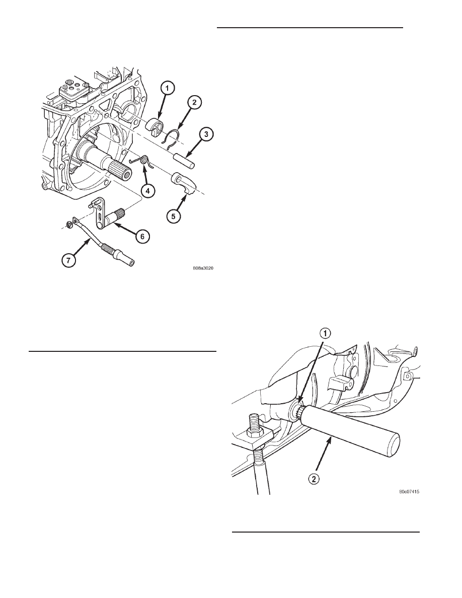
(4) Install a new selector shaft seal using Seal

Installer 8253 (Fig. 28).

Fig. 27 Manual Shaft/Park Lock Components

1 - GUIDE
2 - SNAP-RING
3 - SHAFT
4 - SPRING
5 - PARK PAWL
6 - MANUAL SHAFT/LEVER
7 - PARK ROD

Fig. 28 Install Selector Shaft

1 - SEAL
2 - TOOL 8253

21 - 452

AUTOMATIC TRANSMISSION - 45RFE

AN

AUTOMATIC TRANSMISSION - 45RFE (Continued)

(5) Install the manual selector shaft and retaining

screw. Tighten the manual selector shaft retaining
screw to 28 N·m (250 in.lbs.).

(6) Install the park pawl, spring, and shaft (Fig.

29).

(7) Install the park rod and e-clip (Fig. 29).
(8) Install the park rod guide and snap-ring (Fig.

29).

(9) Install a new dipstick tube seal using Seal

Installer 8254 (Fig. 30).

NOTE: Before final assembly of transmission cen-
terline, the 2C/4C clutch components should be
installed into position and measured as follows:

(10) Install the 2C reaction plate into the trans-

mission case (Fig. 31). The reaction plate is direc-
tional. The plate must be installed with the flat side
toward the front of the transmission.

(11) Install the 2C clutch pack into the transmis-

sion case (Fig. 31).

(12) Install the flat 2C clutch snap-ring into the

transmission case (Fig. 31).

Fig. 29 Manual Shaft/Park Lock Components

1 - GUIDE
2 - SNAP-RING
3 - SHAFT
4 - SPRING
5 - PARK PAWL
6 - MANUAL SHAFT/LEVER
7 - PARK ROD

Fig. 30 Install Dipstick Tube Seal Using Tool 8254

1 - TOOL 8254
2 - SEAL

Fig. 31 Install 2C Clutch Pack

1 - SNAP-RING
2 - PLATE
3 - DISC
4 - REACTION PLATE

AN

AUTOMATIC TRANSMISSION - 45RFE

21 - 453

AUTOMATIC TRANSMISSION - 45RFE (Continued)

(13) Install the 4C retainer/bulkhead into the

transmission case. Make sure that the oil feed holes
are pointing toward the valve body area.

(14) Install

the

4C

retainer/bulkhead

tapered

snap-ring into the transmission case. Make sure that
the open ends of the snap-ring are located in the case
opening toward the valve body area.

(15) Using a feeler gauge through the opening in

the rear of the transmission case, measure the 2C
clutch pack clearance between the 2C reaction plate
and the transmission case at four different points.
The average of these measurements is the 2C clutch
pack clearance. The correct clutch clearance is 0.533-
1.27 mm (0.021-0.050 in.). The reaction plate is not
selective. If the clutch pack clearance is not within
specification, the reaction plate, all the friction discs,
and steels must be replaced.

(16) Remove the 4C retainer/bulkhead and all of

the 2C clutch components from the transmission
case.

(17) Install the low/reverse clutch assembly (Fig.

32). Make sure that the oil feed hole points toward
the valve body area and that the bleed orifice is
aligned with the notch in the rear of the transmis-
sion case.

(18) Install the snap-ring to hold the low/reverse

clutch retainer into the transmission case (Fig. 32).
The snap-ring is tapered and must be installed with
the tapered side forward. Once installed, verify that
the snap-ring is fully seated in the snap-ring groove.

(19) Air check the low/reverse clutch and verify

correct overrunning clutch operation.

(20) Install the number 12 bearing over the output

shaft of the rear planetary gear set and onto the low/
reverse clutch assembly. The flat side of the bearing
goes toward the clutch assembly.

(21) Install the reverse/input planetary assembly

through the low/reverse clutch assembly (Fig. 33).

(22) Install the park sprag onto the output shaft

(Fig. 34).

(23) Install the snap-ring to hold the park sprag

onto the output shaft (Fig. 35).

Fig. 32 Install Low/Reverse Clutch Retainer

1 - LOW/REVERSE OVERRUNNING CLUTCH ASSEMBLY
2 - SNAP-RING

Fig. 33 Install Input/Reverse Planetary Assembly

1 - INPUT/REVERSE PLANETARY ASSEMBLY
2 - BEARING NUMBER 9
3 - BEARING NUMBER 12

21 - 454

AUTOMATIC TRANSMISSION - 45RFE

AN

AUTOMATIC TRANSMISSION - 45RFE (Continued)

(24) Install the 2C reaction plate into the trans-

mission case (Fig. 36). The reaction plate is direc-
tional. The plate must be installed with the flat side
toward the front of the transmission.

(25) Install the 2C clutch pack into the transmis-

sion case (Fig. 36).

(26) Install the number 8 bearing inside the reac-

tion carrier with the round side against the plane-
tary carrier.

(27) Install the reaction planetary gear set and the

number 9 bearing, with the flat side toward the reac-
tion planetary, into the transmission case (Fig. 37).

(28) Install the flat 2C clutch snap-ring into the

transmission case (Fig. 36).

(29) Install the reaction sun gear into the reaction

planetary gear set. Make sure the small shoulder is
facing the front of the transmission (Fig. 37).

(30) Install the number 7 bearing onto the reaction

sun gear with the flat side against the sun gear (Fig.
37).

Fig. 34 Install Park Sprag Gear

1 - PARK SPRAG GEAR

Fig. 35 Install Park Sprag Snap-Ring

1 - SNAP-RING

Fig. 36 Install 2C Clutch Pack

1 - SNAP-RING
2 - PLATE
3 - DISC
4 - REACTION PLATE

AN

AUTOMATIC TRANSMISSION - 45RFE

21 - 455

AUTOMATIC TRANSMISSION - 45RFE (Continued)


Content   ..  700  701  702  703   ..