Dodge Dakota (R1). Manual - part 692


  Index      Dodge     Dodge Dakota (R1) - service repair manual 2000 year


Search            


Content   ..  690  691  692  693   ..


Dodge Dakota (R1). Manual - part 692


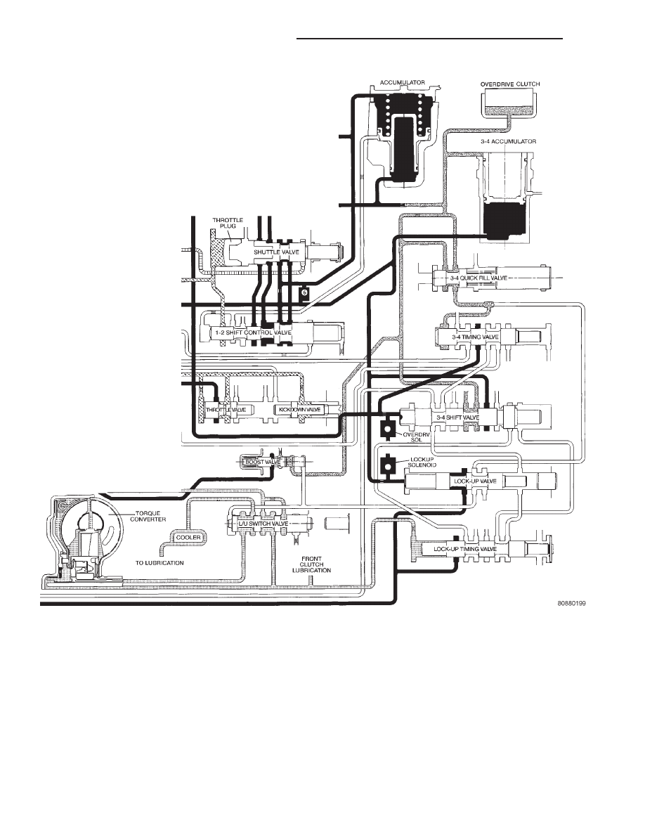
Fig. 280 Switch Valve-Torque Converter Unlocked

21 - 412

AUTOMATIC TRANSMISSION - 46RE

AN

VALVE BODY (Continued)

MANUAL VALVE

The manual valve (Fig. 282) is a relay valve. The

purpose of the manual valve is to direct fluid to the
correct circuit needed for a specific gear or driving
range. The manual valve, as the name implies, is
manually operated by the driver with a lever located
on the side of the valve body. The valve is connected
mechanically by either a cable or linkage to the gear-
shift mechanism. The valve is held in each of its
positions by a spring-loaded roller or ball that
engages the “roostercomb” of the manual valve lever.

CONVERTER CLUTCH LOCK-UP VALVE

The torque converter clutch (TCC) lock-up valve

controls the back (ON) side of the torque converter
clutch. When the PCM energizes the TCC solenoid to
engage the converter clutch piston, pressure is
applied to the TCC lock-up valve which moves to the
right and applies pressure to the torque converter
clutch.

Fig. 281 Switch Valve-Torque Converter Locked

AN

AUTOMATIC TRANSMISSION - 46RE

21 - 413

VALVE BODY (Continued)

CONVERTER CLUTCH LOCK-UP TIMING VALVE

The torque converter clutch (TCC) lock-up timing

valve is there to block any 4-3 downshift until the
TCC is completely unlocked and the clutch is disen-
gaged.

SHUTTLE VALVE

The assembly is contained in a bore in the valve

body above the shift valves. When the manual valve
is positioned in the Drive range, throttle pressure
acts on the throttle plug of the shuttle valve (Fig.
274) to move it against a spring, increasing the
spring force on the shuttle valve. During a part or
full throttle 1-2 upshift, the throttle plug is bottomed
by throttle pressure, holding the shuttle valve to the
right against governor pressure, and opening a
by–pass circuit. The shuttle valve controls the qual-
ity of the kickdown shift by restricting the rate of
fluid discharge from the front clutch and servo
release circuits. During a 3-2 kickdown, fluid dis-
charges through the shuttle by-pass circuit. When
the shuttle valve closes the by-pass circuit, fluid dis-
charge is restricted and controlled for the application
of the front band. During a 2-3 “lift foot” upshift, the
shuttle valve by-passes the restriction to allow full
fluid flow through the by-pass groove for a faster
release of the band.

BOOST VALVE

The boost valve (Fig. 283) provides increased fluid

apply pressure to the overdrive clutch during 3-4
upshifts (Fig. 284), and when accelerating in fourth
gear. The boost valve also serves to increase line
pressure during torque converter lock-up.

Fig. 282 Manual Valve

Fig. 283 Boost Valve Before Lock-up

21 - 414

AUTOMATIC TRANSMISSION - 46RE

AN

VALVE BODY (Continued)

REMOVAL

The valve body can be removed for service without

having to remove the transmission assembly.

The valve body can be disassembled for cleaning

and inspection of the individual components.

The only replaceable valve body components are:
• Manual lever.

• Manual lever washer, seal, E-clip, and shaft

seal.

• Manual lever detent ball.

• Throttle lever.

• Fluid filter.

• Pressure adjusting screw bracket.

• Governor pressure solenoid.

• Governor pressure sensor (includes transmission

temperature thermistor).

• Converter clutch/overdrive solenoid assembly

and harness .

• Governor housing gasket.

• Solenoid case connector O-rings.
(1) Shift transmission into NEUTRAL.
(2) Raise vehicle.
(3) Remove gearshift and throttle levers from shaft

of valve body manual lever.

(4) Disconnect wires at solenoid case connector

(Fig. 285).

(5) Remove the transmission range sensor.
(6) Position drain pan under transmission oil pan.
(7) Remove transmission oil pan and gasket.
(8) Remove fluid filter from valve body.
(9) Remove bolts attaching valve body to transmis-

sion case.

(10) Lower valve body enough to remove accumu-

lator piston and springs.

(11) Work manual lever shaft and electrical con-

nector out of transmission case.

(12) Lower valve body, rotate valve body away

from case, pull park rod out of sprag, and remove
valve body (Fig. 286).

Fig. 284 Boost Valve After Lock-up

Fig. 285 Transmission Case Connector

1 - SOLENOID CASE CONNECTOR
2 - TRANSMISSION RANGE SENSOR

Fig. 286 Valve Body

1 - VALVE BODY
2 - WIRE HARNESS
3 - PARK ROD
4 - GOVERNOR PRESSURE SOLENOID
5 - GOVERNOR PRESSURE SENSOR

AN

AUTOMATIC TRANSMISSION - 46RE

21 - 415

VALVE BODY (Continued)


Content   ..  690  691  692  693   ..