Dodge Dakota (R1). Manual - part 633


  Index      Dodge     Dodge Dakota (R1) - service repair manual 2000 year


Search            


Content   ..  631  632  633  634   ..


Dodge Dakota (R1). Manual - part 633


(20) Position Compressor Tool 6227-1 on clutch

hub.

(21) Compress clutch hub and spring just enough

to place tension on hub and hold it in place.

(22) Slowly compress clutch hub and spring. Com-

press spring and hub only enough to expose ring
grooves for clutch pack snap ring and clutch hub
retaining ring.

(23) Realign clutch pack on hub and seat clutch

discs and plates in clutch drum.

(24) Install direct clutch pack snap-ring (Fig. 173).

Be very sure snap-ring is fully seated in clutch drum
ring groove.

(25) Install clutch hub retaining ring (Fig. 174). Be

very sure retaining ring is fully seated in sun gear
ring groove.

(26) Slowly release press ram, remove compressor

tools and remove geartrain assembly.

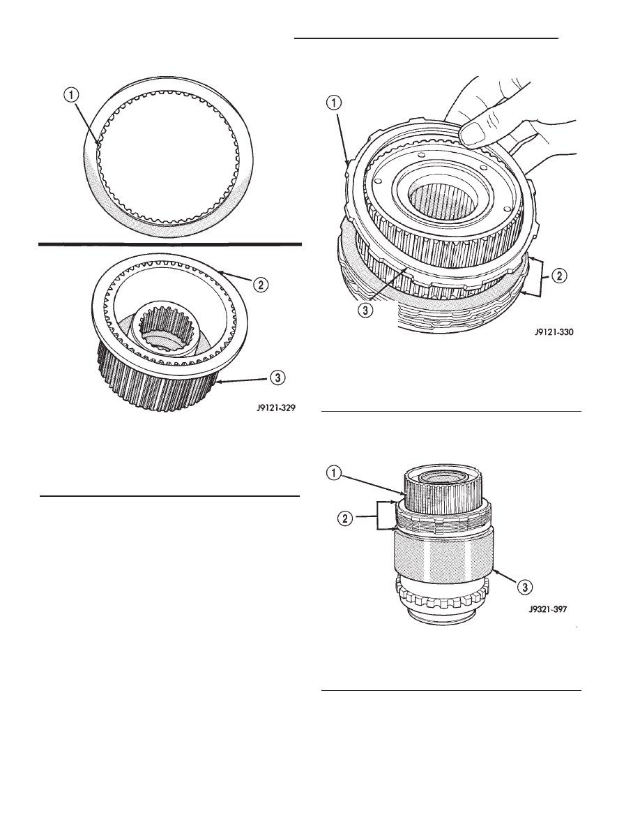
Fig. 170 Correct Position Of Direct Clutch Reaction

Plate

1 - REACTION PLATE COUNTERBORE
2 - DIRECT CLUTCH REACTION PLATE (FLUSH WITH END OF
HUB)
3 - CLUTCH HUB

Fig. 171 Correct Position Of Direct Clutch Pressure

Plate

1 - DIRECT CLUTCH PRESSURE PLATE
2 - CLUTCH PACK
3 - BE SURE SHOULDER SIDE OF PLATE FACES UPWARD

Fig. 172 Direct Clutch

1 - CLUTCH HUB
2 - DIRECT CLUTCH PACK
3 - CLUTCH DRUM

21 - 176

AUTOMATIC TRANSMISSION - 42RE

AN

OVERDRIVE UNIT (Continued)

GEAR CASE

(1) Position park pawl and spring in case and

install park pawl shaft. Verify that end of spring
with 90° bend is hooked to pawl and straight end of
spring is seated against case.

(2) Install pawl shaft retaining bolt. Tighten bolt

to 27 N·m (20 ft. lbs.) torque.

(3) Install park lock reaction plug. Note that plug

has locating pin at rear (Fig. 175). Be sure pin is
seated in hole in case before installing snap-ring.

(4) Install reaction plug snap-ring (Fig. 176). Com-

press snap ring only enough for installation; do not
distort it.

(5) Install new seal in gear case. On 4x4 gear case,

use Tool Handle C-4171 and Installer C-3860-A to
seat seal in case. On 4 x 2 gear case, use same Han-
dle C-4171 and Installer C-3995-A to seat seal in
case.

(6) Verify that tab ends of rear bearing locating

ring extend into access hole in gear case (Fig. 177).

(7) Support geartrain on Tool 6227-1 (Fig. 178). Be

sure tool is securely seated in clutch hub.

(8) Install overdrive gear case on geartrain (Fig.

178).

(9) Expand front bearing locating ring with snap-

ring pliers (Fig. 179). Then slide case downward until
locating ring locks in bearing groove and release
snap-ring.

(10) Install locating ring access cover and gasket

in overdrive unit case (Fig. 180).

Fig. 173 Direct Clutch Pack Snap-Ring Installation

1 - SPECIAL TOOL 6227-1
2 - DIRECT CLUTCH PACK SNAP-RING

Fig. 174 Clutch Hub Retaining Ring Installation

1 - SPECIAL TOOL 6227-1
2 - CLUTCH HUB RETAINING RING

Fig. 175 Reaction Plug Locating Pin And Snap-Ring

1 - REACTION PLUG SNAP-RING (DO NOT OVERCOMPRESS
TO INSTALL)
2 - LOCATING PIN
3 - PARK LOCK REACTION PLUG

Fig. 176 Reaction Plug And Snap-Ring Installation

1 - REACTION PLUG SNAP-RING
2 - SNAP-RING PLIERS

AN

AUTOMATIC TRANSMISSION - 42RE

21 - 177

OVERDRIVE UNIT (Continued)

OVERDRIVE CLUTCH

(1) Install overdrive clutch reaction ring first.

Reaction ring is flat with notched ends (Fig. 181).

(2) Install wave spring on top of reaction ring (Fig.

182). Reaction ring and wave ring both fit in same
ring groove. Use screwdriver to seat each ring
securely in groove. Also ensure that the ends of the
two rings are offset from each other.

NOTE: The 42RE transmission has 3 overdrive
clutch discs and 2 plates.

(3) Assemble overdrive clutch pack (Fig. 183).
(4) Install overdrive clutch reaction plate first.

NOTE: The reaction plate is thinner than the pres-
sure plate in a 42RE transmission.

Fig. 177 Correct Rear Bearing Locating Ring

Position

1 - CASE ACCESS HOLE
2 - TAB ENDS OF LOCATING RING

Fig. 178 Overdrive Gear Case Installation

1 - GEARTRAIN ASSEMBLY
2 - GEAR CASE

Fig. 179 Seating Locating Ring In Rear Bearing

1 - EXPAND BEARING LOCATING RING WITH SNAP-RING
PLIERS
2 - ACCESS HOLE

Fig. 180 Locating Ring Access Cover And Gasket

Installation

1 - TORX SCREWDRIVER (T25)
2 - ACCESS COVER SCREWS

Fig. 181 Overdrive Clutch Reaction Ring Installation

1 - REACTION RING
2 - CLUTCH HUB

21 - 178

AUTOMATIC TRANSMISSION - 42RE

AN

OVERDRIVE UNIT (Continued)

(5) Install first clutch disc followed by first clutch

plate. Then install remaining clutch discs and plates
in same order.

(6) Install clutch pack pressure plate.
(7) Install clutch pack wire-type retaining ring

(Fig. 184).

INTERMEDIATE SHAFT SPACER SELECTION

(1) Place overdrive unit in vertical position. Mount

it on blocks, or in workbench with appropriate size
mounting hole cut into it. Be sure unit is facing
upward for access to direct clutch hub. Also be sure
output shaft is not loaded and internal components
are moved rearward for accurate measurement.

(2) Determine correct thickness intermediate shaft

spacer as follows:

(a) Insert Special Tool 6312 through sun gear,

planetary gear and into pilot bushing in output
shaft. Be sure tool bottoms against planetary
shoulder.

(b) Position Gauge Tool 6311 across face of over-

drive case (Fig. 185). Then position Dial Caliper
C-4962 over gauge tool.

Fig. 183 42RE Overdrive Clutch Components

1 - REACTION PLATE

2 - PRESSURE PLATE

Fig. 182 Overdrive Clutch Wave Spring Installation

1 - WAVE SPRING

Fig. 184 Overdrive Clutch Pack Retaining Ring

Installation

1 - OVERDRIVE CLUTCH PACK RETAINING RING

AN

AUTOMATIC TRANSMISSION - 42RE

21 - 179

OVERDRIVE UNIT (Continued)


Content   ..  631  632  633  634   ..