Dodge Dakota (R1). Manual - part 632


  Index      Dodge     Dodge Dakota (R1) - service repair manual 2000 year


Search            


Content   ..  630  631  632  633   ..


Dodge Dakota (R1). Manual - part 632


ASSEMBLY

GEARTRAIN AND DIRECT CLUTCH

(1) Soak direct clutch and overdrive clutch discs in

Mopar® ATF +4, type 9602, transmission fluid. Allow
discs to soak for 10-20 minutes.

(2) Install new pilot bushing and clutch hub bush-

ing in output shaft if necessary (Fig. 157). Lubricate
bushings with petroleum jelly, or transmission fluid.

(3) Install

annulus

gear

on

output

shaft,

if

removed. Then install annulus gear retaining snap-
ring (Fig. 158).

(4) Align and install clutch drum on annulus gear

(Fig. 159). Be sure drum is engaged in annulus gear
lugs.

(5) Install clutch drum outer retaining ring (Fig.

159).

(6) Slide clutch drum forward and install inner

retaining ring (Fig. 160).

(7) Install rear bearing and snap-ring on output

shaft (Fig. 161). Be sure locating ring groove in bear-
ing is toward rear.

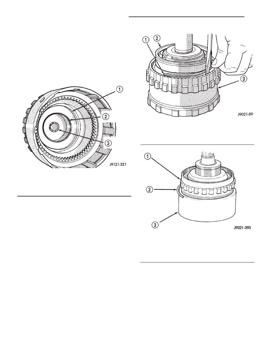
Fig. 157 Output Shaft Pilot Bushing

1 - OUTPUT SHAFT HUB
2 - OVERRUNNING CLUTCH HUB BUSHING
3 - INTERMEDIATE SHAFT PILOT BUSHING

Fig. 158 Annulus Gear Installation

1 - SNAP-RING
2 - OUTPUT SHAFT FRONT BEARING
3 - ANNULUS GEAR

Fig. 159 Clutch Drum And Outer Retaining Ring

Installation

1 - ANNULUS GEAR
2 - OUTER SNAP-RING
3 - CLUTCH DRUM

21 - 172

AUTOMATIC TRANSMISSION - 42RE

AN

OVERDRIVE UNIT (Continued)

(8) Install overrunning clutch on hub (Fig. 162).

Note that clutch only fits one-way. Shoulder on clutch
should seat in small recess at edge of hub.

(9) Install thrust bearing on overrunning clutch

hub. Use generous amount of petroleum jelly to hold
bearing in place for installation. Bearing fits one-way
only. Be sure bearing is seated squarely against hub.
Reinstall bearing if it does not seat squarely.

(10) Install overrunning clutch in output shaft

(Fig. 163). Insert snap-ring pliers in hub splines.
Expand pliers to grip hub. Then install assembly
with counterclockwise, twisting motion.

(11) Install planetary gear in annulus gear (Fig.

164). Be sure planetary pinions are fully seated in
annulus gear before proceeding.

(12) Coat planetary thrust bearing and bearing

contact surface of spring plate with generous amount
of petroleum jelly. This will help hold bearing in
place during installation.

Fig. 160 Clutch Drum Inner Retaining Ring

Installation

1 - ANNULUS GEAR
2 - INNER SNAP-RING
3 - CLUTCH DRUM

Fig. 161 Rear Bearing And Snap-Ring Installation

1 - REAR BEARING
2 - SNAP-RING

Fig. 162 Assembling Overrunning Clutch And Hub

1 - CLUTCH HUB
2 - OVERRUNNING CLUTCH

Fig. 163 Overrunning Clutch Installation

1 - CLUTCH DRUM
2 - OVERRUNNING CLUTCH ASSEMBLY
3 - EXPANDING-TYPE SNAP-RING PLIERS
4 - CLUTCH DRUM
5 - ANNULUS GEAR
6 - OVERRUNNING CLUTCH ASSEMBLY SEATED IN OUTPUT
SHAFT

AN

AUTOMATIC TRANSMISSION - 42RE

21 - 173

OVERDRIVE UNIT (Continued)

(13) Install planetary thrust bearing on sun gear

(Fig. 165). Slide bearing onto gear and seat it against
spring plate as shown. Bearing fits one-way only. If it
does not seat squarely against spring plate, remove
and reposition bearing.

(14) Install assembled sun gear, spring plate and

thrust bearing (Fig. 166). Be sure sun gear and
thrust bearing are fully seated before proceeding.

(15) Mount assembled output shaft, annulus gear,

and clutch drum in shop press. Direct clutch spring,
hub and clutch pack are easier to install with assem-
bly mounted in press.

(16) Align splines in hubs of planetary gear and

overrunning clutch with Alignment tool 6227-2 (Fig.

167). Insert tool through sun gear and into splines of
both hubs. Be sure alignment tool is fully seated
before proceeding.

(17) Install direct clutch spring (Fig. 168). Be sure

spring is properly seated on spring plate.

NOTE: The 42RE transmission has 6 direct clutch
discs and 5 clutch plates.

Fig. 164 Planetary Gear Installation

1 - PLANETARY GEAR
2 - ANNULUS GEAR

Fig. 165 Planetary Thrust Bearing Installation

1 - SPRING PLATE
2 - PLANETARY THRUST BEARING
3 - SUN GEAR

Fig. 166 Sun Gear Installation

1 - SUN GEAR AND SPRING PLATE ASSEMBLY

Fig. 167 Alignment Tool Installation

1 - SPECIAL TOOL 6227-2
2 - PRESS PLATES
3 - ASSEMBLED DRUM AND ANNULUS GEAR
4 - SUN GEAR

21 - 174

AUTOMATIC TRANSMISSION - 42RE

AN

OVERDRIVE UNIT (Continued)

(18) Assemble and install direct clutch pack on

hub as follows:

(a) Assemble clutch pack components (Fig. 169).
(b) Install direct clutch reaction plate on clutch

hub first. Note that one side of reaction plate is
counterbored. Be sure this side faces rearward.
Splines at rear of hub are raised slightly. Counter-
bore in plate fits over raised splines. Plate should
be flush with this end of hub (Fig. 170).

(c) Install first clutch disc followed by a steel

plate until all discs and plates have been installed.

(d) Install pressure plate. This is last clutch

pack item to be installed. Be sure plate is installed
with shoulder side facing upward (Fig. 171).
(19) Install clutch hub and clutch pack on direct

clutch spring (Fig. 172). Be sure hub is started on
sun gear splines before proceeding.

WARNING: THE NEXT STEP IN GEARTRAIN ASSEM-
BLY INVOLVES COMPRESSING THE DIRECT CLUTCH
HUB AND SPRING. IT IS EXTREMELY IMPORTANT
THAT PROPER EQUIPMENT BE USED TO COM-
PRESS THE SPRING AS SPRING FORCE IS APPROX-
IMATELY 830 POUNDS. USE COMPRESSOR TOOL
C-6227-1 AND A HYDRAULIC-TYPE SHOP PRESS
WITH A MINIMUM RAM TRAVEL OF 6 INCHES. THE
PRESS MUST ALSO HAVE A BED THAT CAN BE
ADJUSTED UP OR DOWN AS REQUIRED. RELEASE
CLUTCH SPRING TENSION SLOWLY AND COM-
PLETELY TO AVOID PERSONAL INJURY.

Fig. 169 42RE Direct Clutch Pack Components

1 - REACTION PLATE

2 - PRESSURE PLATE

Fig. 168 Direct Clutch Spring Installation

1 - SPECIAL TOOL 6227-2
2 - DIRECT CLUTCH SPRING
3 - CLUTCH HUB
4 - PRESS PLATES

AN

AUTOMATIC TRANSMISSION - 42RE

21 - 175

OVERDRIVE UNIT (Continued)


Content   ..  630  631  632  633   ..