Dodge Dakota (R1). Manual - part 600


  Index      Dodge     Dodge Dakota (R1) - service repair manual 2000 year


Search            


Content   ..  598  599  600  601   ..


Dodge Dakota (R1). Manual - part 600


REAR ADAPTER HOUSING - 4WD

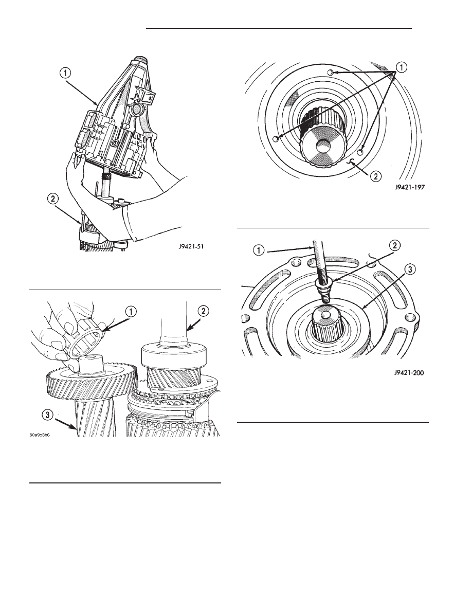
(1) Locate rear seal dimples (Fig. 31). With slide

hammer mounted screw, remove rear seal by insert-
ing screw into one of the seal dimples (Fig. 32).

(2) Remove rear bearing snap ring from output

shaft with snap ring pliers (Fig. 33).

(3) Lift rear adapter housing upward and off

geartrain (Fig. 34).

(4) Remove bearing retainer bolts and remove rear

bearing retainer and rear bearing (Fig. 35). If needed
push or tap bearing out of the housing with a ham-
mer.

(5) Examine condition of bearing bore, counter-

shaft rear bearing race and idler shaft notch in rear
housing. Replace housing if race, bore or notch are
worn or damaged.

GEARTRAIN FROM FIXTURE

(1) Remove

reverse

idler

gear

assembly

from

assembly fixture cup.

(2) Remove 1-2 and fifth-reverse forks from syn-

chro sleeves.

(3) Slide countershaft out of fixture tool.

Fig. 29 REAR HOUSING

1 - REAR HOUSING
2 - SHIFT FORKS AND GEARTRAIN

Fig. 30 COUNTERSHAFT REAR BEARING

1 - COUNTERSHAFT REAR BEARING
2 - OUTPUT SHAFT
3 - COUNTER SHAFT

Fig. 31 DIMPLES IN SEAL FACE - 4WD

1 - LOCATION OF DIMPLES
2 - SEAL FACE

Fig. 32 REAR SEAL - 4WD

1 - SLIDE HAMMER
2 - REMOVER TOOL
3 - REAR SEAL

21 - 44

MANUAL - NV3500

AN

MANUAL - NV3500 (Continued)

(4) Remove output shaft bearing retainer from

rear surface of fifth gear (retainer will drop onto gear
after bolts are removed).

(5) Lift and remove output shaft and gears off

input shaft.

(6) Lift and remove input shaft, pilot bearing and

fourth gear synchro ring from assembly fixture tool.

OUTPUT SHAFT

NOTE: The synchronizer hubs and sleeves are dif-
ferent and must not be intermixed. Remove each
synchronizer unit as an assembly to avoid intermix-
ing parts. Reference mark or tag each synchro hub
and sleeve for correct assembly.

(1) Remove snap ring that secures 3-4 synchro hub

on output shaft.

(2) Remove 3-4 synchro assembly, third gear syn-

chro ring and third gear with shop press and Bearing
Splitter 1130. Position splitter between second and
third gears.

(3) Remove third gear needle bearing (Fig. 36).

Fig. 33 REAR BEARING SNAP RING - 4WD

1 - HEAVY DUTY SNAP RING PLIERS
2 - REAR BEARING SNAP RING
3 - OUTPUT SHAFT

Fig. 34 REAR ADAPTER HOUSING

1 - REAR ADAPTER HOUSING
2 - OUTPUT SHAFT

Fig. 35 REAR ADAPTER HOUSING COMPONENTS

1 - BEARING RETAINER
2 - RETAINER BOLTS (3)
3 - IDLER SHAFT NOTCH
4 - COUNTERSHAFT REAR BEARING RACE
5 - REAR BEARING

Fig. 36 THIRD GEAR NEEDLE BEARING

1 - THIRD GEAR NEEDLE BEARING

AN

MANUAL - NV3500

21 - 45

MANUAL - NV3500 (Continued)

(4) Remove retaining ring that secures two-piece

thrust washer on shaft (Fig. 37). Use a small pry tool
to remove retaining ring.

(5) Remove two-piece thrust washer (Fig. 38). Note

position of washer locating lugs in shaft notches for
installation reference.

(6) Remove second gear and needle bearing (Fig.

39).

(7) Remove second gear synchro ring, synchro fric-

tion cone and synchro cone (Fig. 40).

(8) Remove interm ring.
(9) Remove 1-2 synchro hub snap ring.

Fig. 37 THRUST WASHER

1 - PRY TOOL
2 - THRUST WASHER RETAINING RING

Fig. 38 TWO-PIECE THRUST WASHER

1 - SECOND GEAR
2 - THRUST WASHER (2–PIECE)
3 - WASHER LOCATING LUG

Fig. 39 SECOND GEAR AND NEEDLE BEARING

1 - SECOND GEAR
2 - SECOND GEAR NEEDLE BEARING

Fig. 40 SECOND GEAR SYNCHRO RING AND

CONES

1 - 1-2 SYNCHRO HUB AND SLEEVE
2 - INTERM RING
3 - SYNCHRO FRICTION CONE
4 - SYNCHRO CONE
5 - SYNCHRO RING

21 - 46

MANUAL - NV3500

AN

MANUAL - NV3500 (Continued)

(10) Remove 1-2 synchro hub and sleeve and first

gear from output shaft with press and Bearing Split-
ter 1130 (Fig. 41). Position splitter between first and
reverse gears.

(11) Remove first gear needle bearing (Fig. 42).

(12) Remove output shaft bearing snap ring (Fig.

43).

(13) On 2-wheel drive models, remove output shaft

bearing.

(14) Remove fifth gear (Fig. 44).
(15) Remove fifth gear needle bearing. Spread

bearing apart just enough to clear shoulder on output
shaft (Fig. 45).

Fig. 41 HUB SLEEVE AND 1-2 SYNCHRO

1 - 1-2 SYNCHRO HUB AND SLEEVE
2 - SPECIAL TOOL
1130

Fig. 42 FIRST GEAR NEEDLE BEARING

1 - FIRST GEAR NEEDLE BEARING

Fig. 43 OUTPUT SHAFT BEARING SNAP RING

1 - OUTPUT SHAFT BEARING
2 - BEARING SNAP RING
3 - SNAP RING PLIERS

Fig. 44 FIFTH GEAR

1 - FIFTH GEAR AND SYNCHRO RING

Fig. 45 FIFTH GEAR NEEDLE BEARING

1 - FIFTH GEAR NEEDLE BEARING (SPREAD BEARING TO
CLEAR SHOULDER ON SHAFT)

AN

MANUAL - NV3500

21 - 47

MANUAL - NV3500 (Continued)


Content   ..  598  599  600  601   ..