Dodge Dakota (R1). Manual - part 599


  Index      Dodge     Dodge Dakota (R1) - service repair manual 2000 year


Search            


Content   ..  597  598  599  600   ..


Dodge Dakota (R1). Manual - part 599


SHIFT/FORK SHAFTS AND REVERSE IDLER
SEGMENT

(1) Unseat the roll pin that secures the shift

socket to the shift shaft with Remover 6858 as fol-
lows:

(a) Position remover on the shift shaft. Center

the tool over the roll pin and verify that the tool
legs are firmly seated on the shift socket (Fig. 17).

(b) Tilt the socket toward the side of the case.

This positions the roll pin at a slight angle to avoid
trapping the pin between the gear teeth.

(c) Tighten the tool to press the roll pin down-

ward and out of the shift socket (Fig. 17).

NOTE: Press the roll pin just enough to clear the
shift shaft. Be careful not to push the pin into the
geartrain.

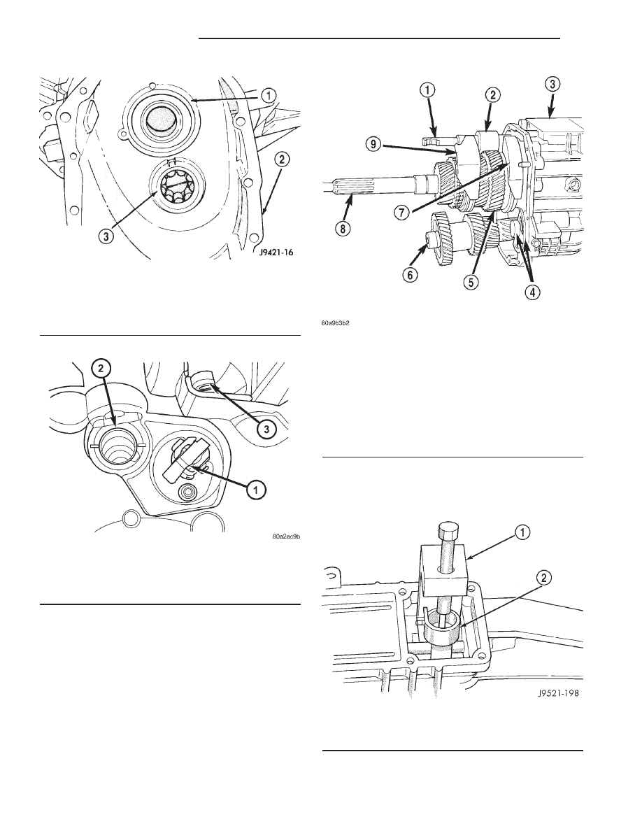
Fig. 14 INPUT SHAFT AND COUNTERSHAFT

BEARING RACE

1 - INPUT SHAFT BEARING
2 - FRONT HOUSING
3 - COUNTERSHAFT FRONT BEARING

Fig. 15 REVERSE BLOCKER

1 - REVERSE BLOCKER
2 - SHIFTER SHAFT BUSHING
3 - VENT

Fig. 16 GEARTRAIN AND SHIFT COMPONENT

1 - SHIFT SHAFT
2 - BUSHING
3 - REAR HOUSING
4 - REVERSE IDLER AND SUPPORT
5 - OUTPUT SHAFT AND GEARS
6 - COUNTERSHAFT
7 - 1-2 FORK
8 - INPUT SHAFT
9 - 3-4 FORK

Fig. 17 SHIFT SOCKET ROLL PIN

1 - SPECIAL TOOL 6858
2 - SHIFT SOCKET

21 - 40

MANUAL - NV3500

AN

MANUAL - NV3500 (Continued)

(2) With a hammer and punch drive out roll pin

that secures shift bushing and lever to shift shaft
(Fig. 18).

NOTE: Use proper size punch to avoid bending the
shift shaft.

(3) Pull shift shaft straight (Fig. 19) out of rear

housing.

(4) Remove shift socket from rear housing (Fig. 20).
(5) Remove lever and bushing (Fig. 21).
(6) Rotate 3-4 fork around synchro sleeve until

fork clears shift arms on 1-2 and fifth-reverse forks,
then remove 3-4 fork (Fig. 22).

(7) Remove the reverse idler shaft support bolt

(front bolt) (Fig. 23).

Fig. 18 SHIFT SHAFT LEVER AND BUSHING ROLL

PIN

1 - PIN PUNCH
2 - BUSHING AND LEVER
3 - SHIFT SHAFT

Fig. 19 SHIFT SHAFT

1 - SHIFTER SHAFT
2 - SHIFTER SHAFT DETENT
3 - 3-4 SHIFT FORK

Fig. 20 SHIFT SOCKET AND ROLL PIN

1 - SHAFT BORE
2 - ROLL PIN
3 - SHIFT SOCKET

Fig. 21 SHIFT SHAFT LEVER AND BUSHING

1 - SHAFT LEVER AND BUSHING
2 - 3-4 FORK

Fig. 22 3-4 SHIFT FORK

1 - 3-4 FORK
2 - 1-2 AND 5TH-REVERSE FORK ARMS
3 - 3-4 SYNCHRO SLEEVE

AN

MANUAL - NV3500

21 - 41

MANUAL - NV3500 (Continued)

(8) Loosen rear reverse idler shaft bolt (rear bolt)

(Fig. 23).

(9) Remove reverse idler shaft support (Fig. 24)

segment by sliding it straight out of housing.

(10) Support geartrain and rear housing on Fix-

ture 6747 as follows:

(a) Adjust height of reverse idler pedestal rod

until the reverse idle shaft bottoms in Cup 8115.

(b) Position Adapters 6747-1A and 6747-2B on

Fixture 6747.

(c) Slide fixture tool onto input shaft, counter-

shaft and idler gear (Fig. 25).

(d) Stand geartrain and rear housing upright on

fixture (Fig. 26). Have helper hold fixture tool in
place while housing and geartrain is being rotated
into upright position.

(11) Remove rear bolt holding reverse idler shaft

in housing.

Fig. 23 REVERSE IDLER SHAFT/SUPPORT BOLT

1 - SUPPORT BOLT
2 - SHAFT BOLT

Fig. 24 IDLER SHAFT SUPPORT

1 - IDLER SHAFT
2 - IDLER SHAFT SUPPORT

Fig. 25 FIXTURE ASSEMBLY

1 - SPECIAL TOOL 6747
2 - SPECIAL TOOL 6747-1A
3 - SPECIAL TOOL 8115
4 - REVERSE IDLER PEDESTAL
5 - SPECIAL TOOL 6747-2B

Fig. 26 GEARTRAIN AND HOUSING ON FIXTURE

1 - INPUT SHAFT
2 - COUNTERSHAFT
3 - SPECIAL TOOL 6747

21 - 42

MANUAL - NV3500

AN

MANUAL - NV3500 (Continued)

REAR HOUSING - 2WD

(1) On 2-wheel drive transmission, remove three

bolts that attach output shaft bearing retainer to
rear case (Fig. 27). Bolts are rear of shift tower open-
ing.

(2) Unseat output shaft bearing from bearing bore

in rear housing. Use plastic/rawhide mallet to tap
rear housing upward and off output shaft bearing as
shown (Fig. 28).

(3) Lift rear housing up and off geartrain (Fig. 29).
(4) Remove countershaft rear bearing from coun-

tershaft (Fig. 30).

(5) Examine condition of bearing bore and idler

shaft notch in rear housing . Replace housing if any
of these components are damaged.

Fig. 27 OUTPUT SHAFT

1 - OUTPUT SHAFT BEARING RETAINER BOLTS (THIRD BOLT
IS AT OPPOSITE SIDE OF CASE)

Fig. 28 REAR HOUSING - 2WD

1 - REAR HOUSING
2 - PLASTIC OR RAWHIDE MALLET
3 - FIXTURE TOOL

AN

MANUAL - NV3500

21 - 43

MANUAL - NV3500 (Continued)


Content   ..  597  598  599  600   ..