Dodge Dakota (R1). Manual - part 563


  Index      Dodge     Dodge Dakota (R1) - service repair manual 2000 year


Search            


Content   ..  561  562  563  564   ..


Dodge Dakota (R1). Manual - part 563


(c) Inspect fitting connector body, plastic retainer

ring and fuel system component for damage.
Replace as necessary.
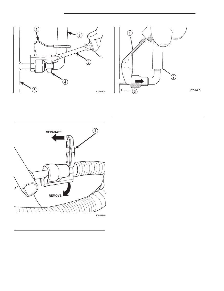
(7) Latch Clips: Depending on vehicle model and

engine, 2 different types of safety latch clips are used
(Fig. 38) or (Fig. 39). Type-1 is tethered to fuel line
and type-2 is not. A special tool will be necessary to
disconnect fuel line after latch clip is removed. The

latch clip may be used on certain fuel line/fuel rail
connection, or to join fuel lines together.

(a) Type 1: Pry up on latch clip with a screw-

driver (Fig. 38).

(b) Type 2: Separate and unlatch 2 small arms

on end of clip (Fig. 39) and swing away from fuel
line.

(c) Slide latch clip toward fuel rail while lifting

with screwdriver.

(d) Insert special fuel line removal tool (Snap-On

number FIH 9055-1 or equivalent) into fuel line
(Fig. 40). Use tool to release locking fingers in end
of line.

(e) With special tool still inserted, pull fuel line

from fuel rail.

(f) After

disconnection,

locking

fingers

will

remain within quick-connect fitting at end of fuel
line.
(8) Disconnect quick-connect fitting from fuel sys-

tem component being serviced.

CONNECTING

(1) Inspect quick-connect fitting body and fuel sys-

tem component for damage. Replace as necessary.

(2) Prior to connecting quick-connect fitting to

component being serviced, check condition of fitting
and component. Clean parts with a lint-free cloth.
Lubricate with clean engine oil.

(3) Insert quick-connect fitting into fuel tube or

fuel system component until built-on stop on fuel
tube or component rests against back of fitting.

(4) Continue pushing until a click is felt.
(5) Single-tab type fitting: Push new tab down

until it locks into place in quick-connect fitting.

Fig. 38 Latch Clip—Type 1

1 - TETHER STRAP
2 - FUEL LINE
3 - SCREWDRIVER
4 - LATCH CLIP
5 - FUEL RAIL

Fig. 39 Latch Clip—Type 2

1 - LATCH CLIP

Fig. 40 Fuel Line Disconnection Using Special Tool

1 - SPECIAL FUEL LINE TOOL
2 - FUEL LINE
3 - FUEL RAIL

14 - 24

FUEL DELIVERY

AN

QUICK CONNECT FITTING (Continued)

(6) Verify a locked condition by firmly pulling on

fuel tube and fitting (15-30 lbs.).

(7) Latch Clip Equipped: Install latch clip (snaps

into position). If latch clip will not fit, this indi-
cates fuel line is not properly installed to fuel
rail (or other fuel line). Recheck fuel line con-
nection.

(8) Connect negative cable to battery.
(9) Start engine and check for leaks.

ROLLOVER VALVE

DESCRIPTION

The fuel tank on 2-door models is equipped with 1

rollover valve. This valve is located on the top of the
fuel tank (Fig. 41). The fuel tank on 4-door models is
equipped with 2 rollover valves. These valves are
also located on the top of the fuel tank (Fig. 42).

OPERATION

The rollover valve(s) will prevent fuel flow through

the fuel tank vent (EVAP) hoses in the event of an
accidental vehicle rollover. The EVAP canister draws
fuel vapors from the fuel tank through this valve(s).

The valve(s) cannot be serviced separately. If

replacement is necessary, the fuel tank must be
replaced. Refer to Fuel Tank Removal/Installation.

REMOVAL

The rollover valves(s) are/is molded into the fuel

tank and are not serviced separately. If replacement
is necessary, the fuel tank must be replaced. Refer to
Fuel Tank Removal/Installation.

INSTALLATION

The rollover valves(s) are/is molded into the fuel

tank and are not serviced separately. If replacement
is necessary, the fuel tank must be replaced. Refer to
Fuel Tank Removal/Installation.

Fig. 41 Rollover Valve Location (2–Door Models)

1 - FILL HOSE
2 - VENT HOSE
3 - ROLLOVER VALVE
4 - LOCKNUT
5 - FUEL PUMP MODULE
6 - FUEL TANK
7 - FUEL FILTER/FUEL PRESSURE REGULATOR

Fig. 42 Rollover Valve Locations (4–Door Models)

1 - FUEL FILTER/FUEL PRESSURE REGULATOR
2 - ROLLOVER VALVE
3 - FUEL TANK SHIELD
4 - LOCKNUT
5 - FUEL PUMP MODULE
6 - ROLLOVER VALVE
7 - FUEL TANK
8 - FILL HOSE
9 - VENT HOSE
10 - PIGTAIL HARNESS

AN

FUEL DELIVERY

14 - 25

QUICK CONNECT FITTING (Continued)

FUEL INJECTION

TABLE OF CONTENTS

page

page

FUEL INJECTION

DIAGNOSIS AND TESTING . . . . . . . . . . . . . . . . . 27

VISUAL INSPECTION - 3.9/5.2/5.9L
ENGINES . . . . . . . . . . . . . . . . . . . . . . . . . . . . . 27
VISUAL INSPECTION - 2.5L ENGINE . . . . . . . . 31

SPECIFICATIONS . . . . . . . . . . . . . . . . . . . . . . . . 34

ACCELERATOR PEDAL

REMOVAL . . . . . . . . . . . . . . . . . . . . . . . . . . . . . . 34
INSTALLATION. . . . . . . . . . . . . . . . . . . . . . . . . . . 34

CRANKSHAFT POSITION SENSOR

DESCRIPTION . . . . . . . . . . . . . . . . . . . . . . . . . . . 35
OPERATION. . . . . . . . . . . . . . . . . . . . . . . . . . . . . 35
REMOVAL . . . . . . . . . . . . . . . . . . . . . . . . . . . . . . 37
INSTALLATION. . . . . . . . . . . . . . . . . . . . . . . . . . . 38

FUEL INJECTOR

DESCRIPTION . . . . . . . . . . . . . . . . . . . . . . . . . . . 39
OPERATION. . . . . . . . . . . . . . . . . . . . . . . . . . . . . 39
DIAGNOSIS AND TESTING . . . . . . . . . . . . . . . . . 39

FUEL INJECTOR TEST. . . . . . . . . . . . . . . . . . . 39

REMOVAL . . . . . . . . . . . . . . . . . . . . . . . . . . . . . . 39
INSTALLATION. . . . . . . . . . . . . . . . . . . . . . . . . . . 40

FUEL PUMP RELAY

DESCRIPTION . . . . . . . . . . . . . . . . . . . . . . . . . . . 40
OPERATION. . . . . . . . . . . . . . . . . . . . . . . . . . . . . 40
REMOVAL . . . . . . . . . . . . . . . . . . . . . . . . . . . . . . 40
INSTALLATION. . . . . . . . . . . . . . . . . . . . . . . . . . . 40

IDLE AIR CONTROL MOTOR

DESCRIPTION . . . . . . . . . . . . . . . . . . . . . . . . . . . 40
OPERATION. . . . . . . . . . . . . . . . . . . . . . . . . . . . . 40
REMOVAL . . . . . . . . . . . . . . . . . . . . . . . . . . . . . . 41
INSTALLATION. . . . . . . . . . . . . . . . . . . . . . . . . . . 42

INTAKE AIR TEMPERATURE SENSOR

DESCRIPTION . . . . . . . . . . . . . . . . . . . . . . . . . . . 42

OPERATION. . . . . . . . . . . . . . . . . . . . . . . . . . . . . 42
REMOVAL . . . . . . . . . . . . . . . . . . . . . . . . . . . . . . 42
INSTALLATION. . . . . . . . . . . . . . . . . . . . . . . . . . . 43

MAP SENSOR

DESCRIPTION . . . . . . . . . . . . . . . . . . . . . . . . . . . 43
OPERATION. . . . . . . . . . . . . . . . . . . . . . . . . . . . . 44
REMOVAL . . . . . . . . . . . . . . . . . . . . . . . . . . . . . . 45
INSTALLATION. . . . . . . . . . . . . . . . . . . . . . . . . . . 46

O2 HEATER RELAY

DESCRIPTION . . . . . . . . . . . . . . . . . . . . . . . . . . . 47
OPERATION. . . . . . . . . . . . . . . . . . . . . . . . . . . . . 47
REMOVAL . . . . . . . . . . . . . . . . . . . . . . . . . . . . . . 47
INSTALLATION. . . . . . . . . . . . . . . . . . . . . . . . . . . 47

O2 SENSOR

DESCRIPTION . . . . . . . . . . . . . . . . . . . . . . . . . . . 47
OPERATION. . . . . . . . . . . . . . . . . . . . . . . . . . . . . 47
REMOVAL . . . . . . . . . . . . . . . . . . . . . . . . . . . . . . 49
INSTALLATION. . . . . . . . . . . . . . . . . . . . . . . . . . . 51

THROTTLE BODY

DESCRIPTION . . . . . . . . . . . . . . . . . . . . . . . . . . . 51
OPERATION. . . . . . . . . . . . . . . . . . . . . . . . . . . . . 51
REMOVAL . . . . . . . . . . . . . . . . . . . . . . . . . . . . . . 52
INSTALLATION. . . . . . . . . . . . . . . . . . . . . . . . . . . 53

THROTTLE CONTROL CABLE

REMOVAL . . . . . . . . . . . . . . . . . . . . . . . . . . . . . . 54
INSTALLATION. . . . . . . . . . . . . . . . . . . . . . . . . . . 55

THROTTLE POSITION SENSOR

DESCRIPTION . . . . . . . . . . . . . . . . . . . . . . . . . . . 56
OPERATION. . . . . . . . . . . . . . . . . . . . . . . . . . . . . 56
REMOVAL . . . . . . . . . . . . . . . . . . . . . . . . . . . . . . 56
INSTALLATION. . . . . . . . . . . . . . . . . . . . . . . . . . . 57

14 - 26

FUEL INJECTION

AN

FUEL INJECTION

DIAGNOSIS AND TESTING - VISUAL
INSPECTION—3.9L/5.2L/5.9L ENGINES

A visual inspection for loose, disconnected or incor-

rectly routed wires and hoses should be made. This
should be done before attempting to diagnose or ser-
vice the fuel injection system. A visual check will
help spot these faults and save unnecessary test and
diagnostic time. A thorough visual inspection will
include the following checks:

(1) Verify three 32–way electrical connectors are

fully inserted into connector of powertrain control
module (PCM) (Fig. 1).

(2) Inspect battery cable connections. Be sure they

are clean and tight.

(3) Inspect fuel pump relay and air conditioning

compressor clutch relay (if equipped). Inspect ASD
relay connections. Inspect starter motor relay connec-
tions. Inspect relays for signs of physical damage and
corrosion. The relays are located in Power Distribu-
tion Center (PDC) (Fig. 2). Refer to label on PDC
cover for relay location.

(4) Inspect ignition coil connections. Verify coil sec-

ondary cable is firmly connected to coil (Fig. 3).

(5) Verify distributor cap is correctly attached to

distributor. Be sure spark plug cables are firmly con-
nected to the distributor cap and the spark plugs are
in their correct firing order. Be sure coil cable is

firmly connected to distributor cap and coil. Be sure
camshaft position sensor wire connector (at the dis-
tributor) is firmly connected to harness connector.
Inspect spark plug condition. Refer to 8, Ignition.
Connect vehicle to an oscilloscope and inspect spark
events for fouled or damaged spark plugs or cables.

(6) Verify generator output wire, generator connec-

tor and ground wire are firmly connected to genera-
tor.

(7) Inspect system body grounds for loose or dirty

connections. Refer to 8, Wiring for ground locations.

Fig. 1 Powertrain Control Module (PCM)

1 - RIGHT FRONT FENDER
2 - PCM MOUNTING BOLTS (3)
3 - 32–WAY CONNECTORS (3)
4 - COVER
5 - POWERTRAIN CONTROL MODULE (PCM)

Fig. 2 Power Distribution Center (PDC)

1 - POWER DISTRIBUTION CENTER (PDC)

Fig. 3 Ignition Coil—3.9/5.2/5.9L Engines—Typical

1 - ACCESSORY DRIVE BELT TENSIONER
2 - COIL CONNECTOR
3 - IGNITION COIL
4 - COIL MOUNTING BOLTS

AN

FUEL INJECTION

14 - 27


Content   ..  561  562  563  564   ..