Dodge Dakota (R1). Manual - part 562


  Index      Dodge     Dodge Dakota (R1) - service repair manual 2000 year


Search            


Content   ..  560  561  562  563   ..


Dodge Dakota (R1). Manual - part 562


(9) If equipped with a 2–piece driveshaft, the

crossmember located below the fuel tank must be
removed.

(a) Remove bolts/nuts securing driveshaft center

bearing carrier bracket to crossmember.

(b) Raise and support driveshaft and carrier

bracket assembly using a length of rope.

(c) Center punch all rivets.
(d) Drill out rivets with a 3/8” drill bit. Do not

use a larger bit, as holes in crossmember and vehi-
cle frame may become too large.

(e) Remove crossmember from vehicle.
(f) Remove remaining rivet material from cross-

member and vehicle frame.
(10) If equipped, remove fuel tank skid plate.

Refer to 23, Body

(11) Place and secure a transmission jack under

center of fuel tank and apply slight pressure.

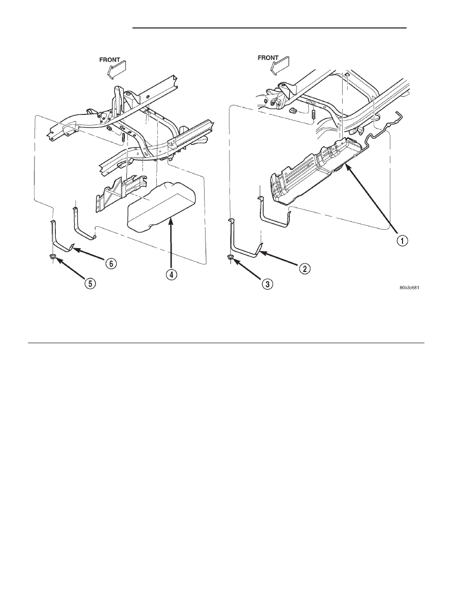
(12) Remove two tank mounting nuts from mount-

ing straps (Fig. 30). Position tank mounting straps to

side of vehicle and lower tank just enough to allow
access to connections at top of tank.

(13) Clean quick-connect fittings of any dirt/con-

taminants before removal.

(14) Disconnect fuel supply line from fuel filter/

fuel pressure regulator fitting at top of tank. Refer to
Quick-Connect Fittings for procedures.

(15) Disconnect fuel vapor line(s) from rollover

valve(s) at top of tank.

(16) Disconnect electrical connector at pump mod-

ule at top of tank.

(17) Lower tank from vehicle. On certain models,

the tank must first be moved rearward, and then
down, for removal.

(18) Remove tank from hydraulic jack.
(19) If fuel pump module requires service, refer to

Fuel Pump Module Removal/Installation.

(20) If fill and vent hoses are to be removed from

tank, note their position on fuel tank fittings before
removal.

Fig. 30 Fuel Tank Mounting

1 - FUEL TANK (2—DOOR)
2 - STRAPS (2)
3 - NUTS (2)
4 - FUEL TANK (2—DOOR)

5 - NUTS (2)
6 - STRAPS (2)

14 - 20

FUEL DELIVERY

AN

FUEL TANK (Continued)

INSTALLATION

(1) If fuel pump module is being installed, refer to

Fuel Pump Module Removal/Installation.

(2) Install fill and vent hoses to tank fittings.
(3) Place and secure fuel tank to transmission

jack.

(4) Raise tank up enough to connect fuel line, elec-

trical connector and vapor hoses to top of fuel tank.
Refer to Quick-Connect Fittings for fuel line proce-
dures.

(5) Continue raising tank into position and install

mounting straps and nuts. Tighten nuts to 27–54
N·m (20–40 ft. lbs.) torque. Do not over tighten
mounting strap nuts.

(6) Remove transmission jack.
(7) If equipped, install fuel tank skid plate. Refer

to 23, Body.

(8) If equipped with a 2–piece driveshaft:

(a) Obtain new bolts and nuts to secure cross-

member to frame. Use the same OEM bolts/nuts
that are used to secure the upper fuel tank cross-
member to the vehicle frame.

(b) Position

crossmember

to

vehicle

frame.

Install bolts and tighten to 54 N·m (40 ft. lbs.)
torque.

(c) Position

driveshaft

and

carrier

bracket

assembly to crossmember.

(d) Install bolts and tighten to 54 N·m (40 ft.

lbs.) torque.
(9) Install fill and vent hoses to fill and vent tubes.
(10) Install splash shield in front of left/rear

wheelhouse.

(11) Connect negative cable to battery.
(12) Refill fuel tank and install fill cap.
(13) Inspect all hoses and lines for leaks.

INLET FILTER

REMOVAL

The fuel pump inlet filter (strainer) is located on

the bottom of the fuel pump module (Fig. 31) or (Fig.
32). The fuel pump module is located inside of fuel
tank.

(1) Remove fuel tank. Refer to Fuel Tank Removal/

Installation.

(2) Remove fuel pump module. Refer to Fuel Pump

Module Removal/Installation.

(3) 2 Door Models: Remove filter by carefully pry-

ing 2 lock tabs at bottom of module with 2 screwdriv-
ers. Filter is snapped to module.

(4) 4 Door Models: Remove filter by carefully pry-

ing it from bottom of pump module with 2 screwdriv-
ers. Filter is snapped to module.

(5) Clean bottom of pump module.

INSTALLATION

The fuel pump inlet filter (strainer) is located on

the bottom of the fuel pump module (Fig. 31) or (Fig.
32). The fuel pump module is located inside of fuel
tank.

Fig. 31 Fuel Pump Inlet Filter—2 Door Models

1 - FUEL PUMP INLET FILTER
2 - LOCK TABS (2)
3 - FUEL PUMP MODULE (BOTTOM)

Fig. 32 Fuel Pump Inlet Filter—4 Door Models

1 - FUEL PUMP MODULE
2 - FUEL PUMP INLET FILTER

AN

FUEL DELIVERY

14 - 21

FUEL TANK (Continued)

(1) Snap new filter to bottom of module. Be sure

o-ring is in correct position.

(2) Install fuel pump module. Refer to Fuel Pump

Module Removal/Installation.

(3) Install fuel tank. Refer to Fuel Tank Removal/

Installation.

QUICK CONNECT FITTING

DESCRIPTION

Different types of quick-connect fittings are used to

attach various fuel system components, lines and
tubes. These are: a single-tab type, a two-tab type or
a plastic retainer ring type. Some are equipped with
safety latch clips. Some may require the use of a spe-
cial tool for disconnection and removal. Refer to
Quick-Connect Fittings Removal/Installation for more
information.

CAUTION: The interior components (o-rings, clips)
of quick-connect fittings are not serviced sepa-
rately, but new plastic spacers are available for
some types. If service parts are not available, do
not attempt to repair the damaged fitting or fuel line
(tube). If repair is necessary, replace the complete
fuel line (tube) assembly.

STANDARD PROCEDURE - QUICK-CONNECT
FITTINGS

Also refer to Fuel Tubes/Lines/Hoses and Clamps.
Different types of quick-connect fittings are used to

attach various fuel system components, lines and
tubes. These are: a single-tab type, a two-tab type or
a plastic retainer ring type. Safety latch clips are
used on certain components/lines. Certain fittings
may require use of a special tool for disconnection.

DISCONNECTING

WARNING: THE FUEL SYSTEM IS UNDER A CON-
STANT PRESSURE (EVEN WITH ENGINE OFF).
BEFORE SERVICING ANY FUEL SYSTEM HOSE,
FITTING OR LINE, FUEL SYSTEM PRESSURE MUST
BE RELEASED. REFER TO FUEL SYSTEM PRES-
SURE RELEASE PROCEDURE.

CAUTION: The interior components (o-rings, spac-
ers) of some types of quick-connect fitting are not
serviced separately. If service parts are not avail-
able, do not attempt to repair a damaged fitting or
fuel line. If repair is necessary, replace complete
fuel line assembly.

(1) Perform fuel pressure release procedure. Refer

to Fuel Pressure Release Procedure.

(2) Disconnect negative battery cable from battery.
(3) Clean fitting of any foreign material before dis-

assembly.

(4) Single-Tab Type Fitting: This type of fitting

is equipped with a single pull tab (Fig. 33). The tab
is removable. After tab is removed, quick-connect fit-
ting can be separated from fuel system component.

(a) Press release tab on side of fitting to release

pull tab (Fig. 34). If release tab is not pressed
prior to releasing pull tab, pull tab will be
damaged.

(b) While pressing release tab on side of fitting,

use screwdriver to pry up pull tab (Fig. 34).

(c) Raise pull tab until it separates from quick-

connect fitting (Fig. 35).
(5) Two-Tab Type Fitting: This type of fitting is

equipped with tabs located on both sides of fitting
(Fig. 36). The tabs are supplied for disconnecting
quick-connect fitting from component being serviced.

(a) To disconnect quick-connect fitting, squeeze

plastic retainer tabs (Fig. 36) against sides of
quick-connect fitting with your fingers. Tool use is
not required for removal and may damage plastic
retainer.

(b) Pull fitting from fuel system component

being serviced.

(c) The plastic retainer will remain on compo-

nent being serviced after fitting is disconnected.
The o-rings and spacer will remain in quick-con-
nect fitting connector body.

Fig. 33 Single-Tab Type Fitting

1 - PULL TAB
2 - QUICK-CONNECT FITTING
3 - PRESS HERE TO REMOVE PULL TAB
4 - INSERTED TUBE END

14 - 22

FUEL DELIVERY

AN

INLET FILTER (Continued)

(6) Plastic Retainer Ring Type Fitting: This

type of fitting can be identified by the use of a full-
round plastic retainer ring (Fig. 37) usually black in
color.

(a) To release fuel system component from quick-

connect fitting, firmly push fitting towards compo-
nent being serviced while firmly pushing plastic
retainer ring into fitting (Fig. 37). With plastic ring
depressed, pull fitting from component. The plas-
tic retainer ring must be pressed squarely
into fitting body. If this retainer is cocked
during removal, it may be difficult to discon-
nect fitting. Use an open-end wrench on

shoulder of plastic retainer ring to aid in dis-
connection.

(b) After disconnection, plastic retainer ring will

remain with quick-connect fitting connector body.

Fig. 34 Disconnecting Single-Tab Type Fitting

1 - PULL TAB
2 - SCREWDRIVER
3 - QUICK-CONNECT FITTING

Fig. 35 Removing Pull Tab

1 - FUEL TUBE OR FUEL SYSTEM COMPONENT
2 - PULL TAB
3 - QUICK-CONNECT FITTING
4 - FUEL TUBE STOP

Fig. 36 Typical Two-Tab Type Quick-Connect Fitting

1 - TAB(S)
2 - QUICK-CONNECT FITTING

Fig. 37 Plastic Retainer Ring Type Fitting

1 - FUEL TUBE
2 - QUICK CONNECT FITTING
3 - PUSH
4 - PLASTIC RETAINER
5 - PUSH
6 - PUSH
7 - PUSH
8 - PUSH

AN

FUEL DELIVERY

14 - 23

QUICK CONNECT FITTING (Continued)


Content   ..  560  561  562  563   ..