Dodge Dakota (R1). Manual - part 542
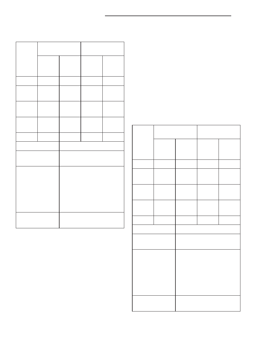
PISTON MEASUREMENT CHART
PISTON
A DIA = PISTON
BORE
SIZE
DIAMETER
DIAMETER
MIN.
MAX.
MIN.
MAX.
mm
(in.)
mm
(in.)
mm
(in.)
mm (in.)
A
—
—
—
—
B
101.580
101.592
101.605
101.618
(3.9992)
(3.9997)
(4.0002)
(4.0007)
C
101.592
101.605
101.618
101.630
(3.9997)
(4.0002)
(4.0007)
(4.0012)
D
101.605
101.618
101.630
101.643
(4.0002)
(4.0007)
(4.0012)
(4.0017)
E
—
—
—
—
DESCRIPTION
SPECIFICATION
PISTON PIN BORE
25.007 - 25.015 mm
(.9845 - .9848 in.)
RING GROOVE
HEIGHT
(OIL RAIL)
4.033 - 4.058 mm
(.1588 - .1598 in.)
(COMPRESSION
RAIL)
1.529 - 1.554 mm
(.0602 - .0612 in.)
TOTAL FINISHED
470.8 ± 2 grams
WEIGHT
(16.607 ± .0706 ounces)
REMOVAL
(1) Remove the engine from the vehicle.
(2) Remove the cylinder head.
(3) Remove the oil pan.
(4) Remove top ridge of cylinder bores with a reli-
able ridge reamer before removing pistons from cyl-
inder block. Be sure to keep tops of pistons covered
during this operation.
(5) Be sure the connecting rod and connecting rod
cap are identified with the cylinder number. Remove
connecting rod cap. Install connecting rod bolt guide
set on connecting rod bolts.
(6) Pistons and connecting rods must be removed
from top of cylinder block. When removing piston and
connecting rod assemblies, rotate crankshaft to cen-
ter the connecting rod in the cylinder bore and at
BDC. Be careful not to nick crankshaft journals.
(7) After removal, install bearing cap on the mat-
ing rod.
INSPECTION
Check the connecting rod journal for excessive
wear, taper and scoring.
Check the cylinder block bore for out-of-round,
taper, scoring and scuffing.
Check the pistons for taper and elliptical shape
before they are fitted into the cylinder bore (Fig. 35).
PISTON MEASUREMENT CHART
PISTON
A DIA = PISTON
BORE
SIZE
DIAMETER
DIAMETER
MIN.
MAX.
MIN.
MAX.
mm
(in.)
mm
(in.)
mm
(in.)
mm (in.)
A
—
—
—
—
B
101.580
101.592
101.605
101.618
(3.9992)
(3.9997)
(4.0002)
(4.0007)
C
101.592
101.605
101.618
101.630
(3.9997)
(4.0002)
(4.0007)
(4.0012)
D
101.605
101.618
101.630
101.643
(4.0002)
(4.0007)
(4.0012)
(4.0017)
E
—
—
—
—
DESCRIPTION
SPECIFICATION
PISTON PIN BORE
25.007 - 25.015 mm
(.9845 - .9848 in.)
RING GROOVE
HEIGHT
(OIL RAIL)
4.033 - 4.058 mm
(.1588 - .1598 in.)
(COMPRESSION
RAIL)
1.529 - 1.554 mm
(.0602 - .0612 in.)
TOTAL FINISHED
470.8 ± 2 grams
WEIGHT
(16.607 ± .0706 ounces)
9a - 86
ENGINE 5.2L INTERNATIONAL
R1
PISTON & CONNECTING ROD (Continued)