Dodge Dakota (R1). Manual - part 540
(16) Install timing case cover.
(17) Install cylinder head covers.
(18) Install intake manifold.
(19) Install the engine cover.
(20) Install the A/C Condenser (if equipped).
(21) Install the radiator. (Refer to 7 - COOLING/
ENGINE/RADIATOR - INSTALLATION) for the cor-
rect procedures.
(22) Refill cooling system. (Refer to 7 - COOLING/
ENGINE - STANDARD PROCEDURE) for the cor-
rect procedures.
(23) Start engine, and check for leaks.
CONNECTING ROD BEARINGS
STANDARD PROCEDURE - CONNECTING ROD
BEARING - FITTING
Fit all rods on a bank until completed. DO NOT
alternate from one bank to another, because connect-
ing rods and pistons are not interchangeable from
one bank to another.
The bearing caps are not interchangeable and
should be marked at removal to ensure correct
assembly.
Each bearing cap has a small V-groove across the
parting face. When installing the lower bearing shell,
make certain that the V-groove in the shell is in line
with the V-groove in the cap. This provides lubrica-
tion of the cylinder wall in the opposite bank.
The bearing shells must be installed so that the
tangs are in the machined grooves in the rods and
caps.
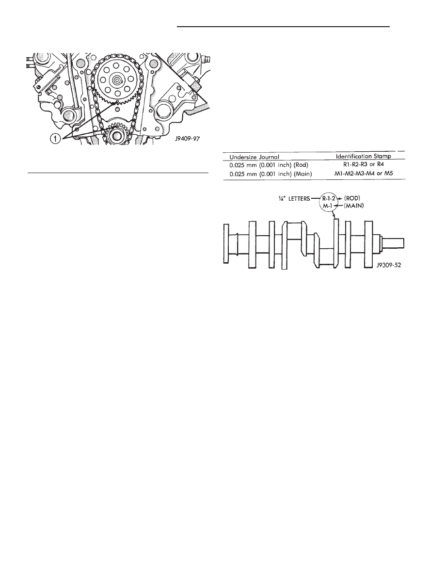
Limits of taper or out-of-round on any crankshaft
journals should be held to 0.025 mm (0.001 in.).
Bearings are available in 0.025 mm (0.001 in.), 0.051
mm (0.002 in.), 0.076 mm (0.003 in.), 0.254 mm
(0.010 in.) and 0.305 mm (0.012 in.) undersize.
Install the bearings in pairs. DO NOT use a new
bearing half with an old bearing half. DO NOT
file the rods or bearing caps.
CRANKSHAFT
DESCRIPTION
The crankshaft is of a cast nodular steel splayed
type design, with five main bearing journals. The
crankshaft is located at the bottom of the engine
block and is held in place with five main bearing
caps. The number 3 counterweight is the location for
journal size identification (Fig. 21).
OPERATION
The crankshaft transfers force generated by com-
bustion within the cylinder bores to the flywheel or
flexplate.
REMOVAL
NOTE: This procedure can be done in vehicle. How-
ever the transmission must be removed first.
(1) If crankshaft is to be removed while engine is
in vehicle remove the transmission. Refer to Group
21, for correct procedure.
(2) Remove the oil pan.
(3) Remove the oil pump from the rear main bear-
ing cap.
(4) Remove the vibration damper.
(5) Remove the timing chain cover.
(6) Identify
rod
bearing
caps
before
removal.
Remove rod bearing caps with bearings.
CAUTION:
Support
crankshaft
before
removing
main bearing caps, failure to do so will allow the
crankshaft to fall damaging the crankshaft.
(7) Using a suitable jack, support the crankshaft.
(8) Identify main bearing caps before removal.
Remove main bearing caps and bearings one at a
time.
Fig. 20 Alignment of Timing Marks
1 - TIMING MARKS
Fig. 21 Crankshaft with Journal Size Identification
9a - 78
ENGINE 5.2L INTERNATIONAL
R1
CAMSHAFT & BEARINGS (Continued)