Dodge Dakota (R1). Manual - part 538


  Index      Dodge     Dodge Dakota (R1) - service repair manual 2000 year


Search            


Content   ..  536  537  538  539   ..


Dodge Dakota (R1). Manual - part 538


(13) Install the fuel supply line (Refer to 14 -

FUEL

SYSTEM/FUEL

DELIVERY/QUICK

CON-

NECT FITTING - STANDARD PROCEDURE).

(14) Install the generator and drive belt (Refer to 8

-

ELECTRICAL/CHARGING/GENERATOR

-

INSTALLATION) and (Refer to 7 - COOLING/AC-
CESSORY

DRIVE/DRIVE

BELTS

-

INSTALLA-

TION). Tighten generator mounting bolt to 41 N·m
(30 ft. lbs.) torque.

(15) Install

the

intake

manifold-to-generator

bracket support rod. Tighten the bolts.

(16) Place the cylinder head cover gaskets in posi-

tion and install cylinder head covers (Refer to 9 -
ENGINE/CYLINDER

HEAD/CYLINDER

HEAD

COVER(S) - INSTALLATION). Tighten the bolts to
11 N·m (95 in. lbs.) torque.

(17) Install closed crankcase ventilation system.
(18) Connect the evaporation control system.
(19) Install the air cleaner assembly and air inlet

hose.

(20) Install the heat shields. Tighten the bolts to

41 N·m (30 ft. lbs.) torque.

(21) Fill cooling system (Refer to 7 - COOLING/

ENGINE - STANDARD PROCEDURE).

(22) Connect the battery negative cable.

CYLINDER HEAD COVER
GASKET

DESCRIPTION

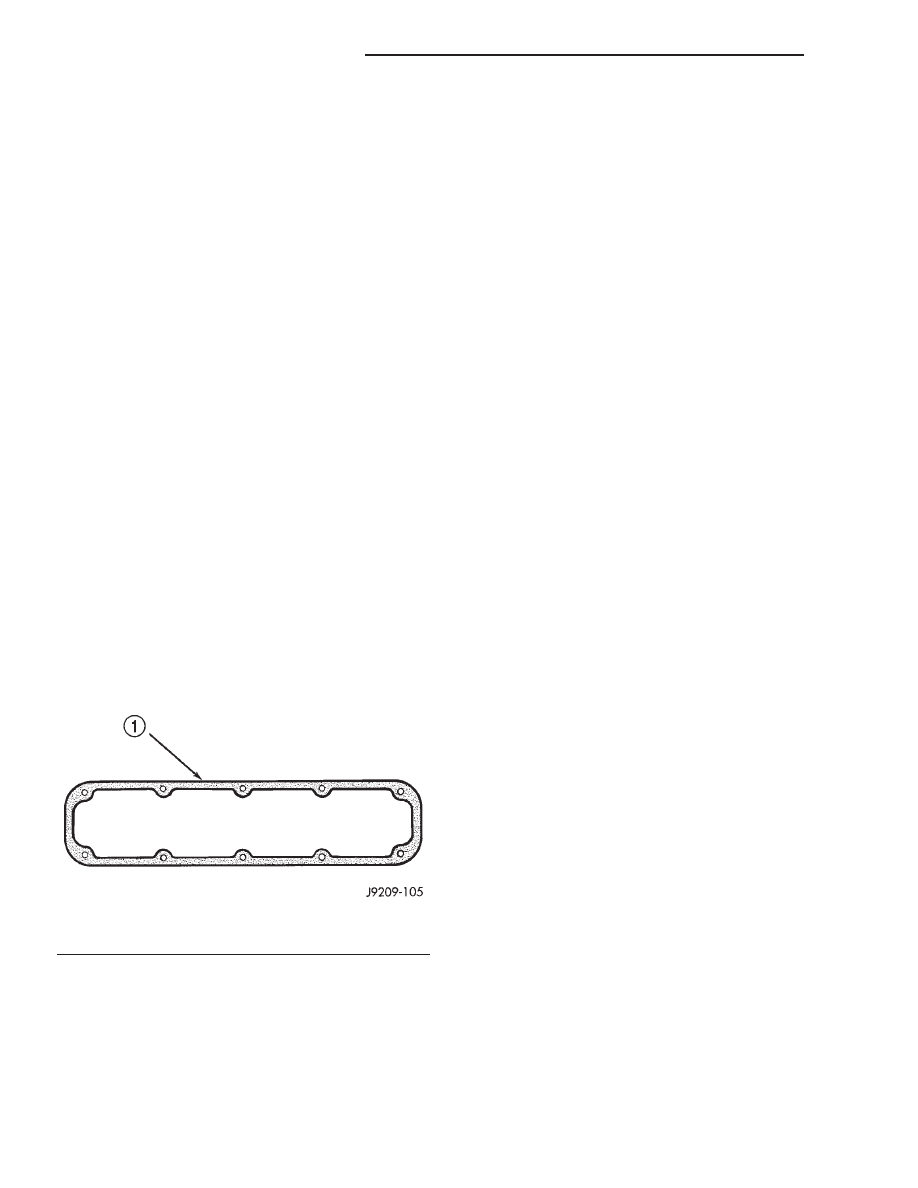
The cylinder head cover gasket (Fig. 5) is a steel-

backed silicone gasket, designed for long life usage.

The steel-backed silicone gasket is designed to seal

the cylinder head cover for long periods of time
through extensive heat and cold, without failure. The
gasket is designed to be reusable.

CYLINDER HEAD COVER(S)

REMOVAL

NOTE: A steel backed silicon gasket is used with
the cylinder head cover (Fig. 5). This gasket can be
used again.

(1) Disconnect the negative cable from the battery.
(2) Disconnect closed ventilation system and evap-

oration control system from cylinder head cover.

(3) Remove the air inlet hose.
(4) Remove cylinder head cover and gasket. The

gasket may be used again.

CLEANING

Clean cylinder head cover gasket surface.
Clean head rail, if necessary.

INSPECTION

Inspect cover for distortion and straighten, if nec-

essary.

Check the gasket for use in head cover installation.

If damaged, use a new gasket.

INSTALLATION

(1) The cylinder head cover gasket can be used

again. Install the gasket onto the head rail.

(2) Position the cylinder head cover onto the gas-

ket. Tighten the bolts to 11 N·m (95 in. lbs.) torque.

(3) Install closed crankcase ventilation system and

evaporation control system.

(4) Install the air inlet hose.
(5) Connect the negative cable to the battery.

INTAKE/EXHAUST VALVES &
SEATS

DESCRIPTION - VALVES AND VALVE SPRINGS

Both the intake and exhaust valves are made of

steel. The intake valve is 48.768 mm (1.92 inches) in
diameter and the exhaust valve is 41.148 mm (1.62
inches) in diameter and has a 2.032 mm (0.080 inch)
wafer interia welded to the tip for durability. These
valves are not splayed.

STANDARD PROCEDURE - VALVE SERVICE

VALVE CLEANING

Clean valves thoroughly. Discard burned, warped

and cracked valves.

Remove carbon and varnish deposits from inside of

valve guides with a reliable guide cleaner.

Fig. 5 Cylinder Head Cover Gasket V-8 Gas Engines

1 - CYLINDER HEAD COVER GASKET

9a - 70

ENGINE 5.2L INTERNATIONAL

R1

CYLINDER HEAD (Continued)

VALVE INSPECTION

Measure valve stems for wear. If wear exceeds

0.051 mm (0.002 inch), replace the valve.

VALVE GUIDES

Measure valve stem guide clearance as follows:
(1) Install Valve Guide Sleeve Tool C-3973 over

valve stem and install valve (Fig. 6). The special
sleeve places the valve at the correct height for
checking with a dial indicator.

(2) Attach Dial Indicator Tool C-3339 to cylinder

head and set it at right angle of valve stem being
measured (Fig. 7) .

(3) Move valve to and from the indicator. The total

dial indicator reading should not exceed 0.432 mm
(0.017 inch). Ream the guides for valves with over-
size stems if dial indicator reading is excessive or if
the stems are scuffed or scored.

Service valves with oversize stems are available as

shown below.

REAMER SIZES

REAMER O/S

VALVE GUIDE SIZE

0.076 mm (0.003 in.)

8.026 - 8.052 mm

(0.316 - 0.317 in.)

0.381 mm (0.015 in.)

8.331 - 8.357 mm

(0.328 - 0.329 in.)

Slowly turn reamer by hand and clean guide thor-

oughly before installing new valve. Ream the valve
guides from standard to 0.381 mm (0.015 inch).
Use a 2 step procedure so the valve guides are
reamed true in relation to the valve seat:

• Step 1—Ream to 0.0763 mm (0.003 inch).

• Step 2—Ream to 0.381 mm (0.015 inch).

REFACING VALVES AND VALVE SEATS

The intake and exhaust valves have a 43-1/4° to

43-3/4° face angle and a 44-1/4° to 44-3/4° seat angle
(Fig. 8).

Fig. 6 Positioning Valve with Tool C-3973

1 - VALVE
2 - SPACER TOOL

Fig. 7 Measuring Valve Guide Wear

1 - VALVE
2 - SPECIAL TOOL C-3339

Fig. 8 Valve Face and Seat Angles

1 - CONTACT POINT
A,B,C and D Refer to VALVE FACE AND VALVE SEAT ANGLE
CHART

R1

ENGINE 5.2L INTERNATIONAL

9a - 71

INTAKE/EXHAUST VALVES & SEATS (Continued)

VALVE FACE AND VALVE SEAT ANGLE CHART

ITEM

DESCRIPTION

SPECIFICATION

A

SEAT WIDTH–

1.016 - 1.524 mm

INTAKE

(0.040 - 0.060 in.)

SEAT WIDTH–

1.524 - 2.032 mm

EXHAUST

(0.060 - 0.080 in.)

B

FACE ANGLE

(INT. and EXT.)

43¼° - 43¾°

C

SEAT ANGLE

(INT. and EXT.)

44¼° - 44¾°

D

CONTACT

SURFACE

VALVES

Inspect the remaining margin after the valves are

refaced (Fig. 9). Valves with less than 1.190 mm
(0.047 inch) margin should be discarded.

VALVE SEATS

CAUTION: DO NOT un-shroud valves during valve
seat refacing (Fig. 10).

(1) When refacing valve seats, it is important that

the correct size valve guide pilot be used for reseat-
ing stones. A true and complete surface must be
obtained.

(2) Measure the concentricity of valve seat using a

dial indicator. Total runout should not exceed 0.051
mm (0.002 inch) total indicator reading.

(3) Inspect the valve seat with Prussian blue to

determine where the valve contacts the seat. To do
this, coat valve seat LIGHTLYwith Prussian blue
then set valve in place. Rotate the valve with light
pressure. If the blue is transferred to the center of
valve face, contact is satisfactory. If the blue is trans-
ferred to the top edge of valve face, lower valve seat
with a 15° stone. If the blue is transferred to bottom
edge of valve face raise valve seat with a 60° stone.

(4) When seat is properly positioned the width of

intake seats should be 1.016-1.524 mm (0.040-0.060
inch). The width of the exhaust seats should be
1.524-2.032 mm (0.060-0.080 inch).

VALVE SPRING INSPECTION

Whenever valves have been removed for inspection,

reconditioning or replacement, valve springs should
be tested. As an example the compression length of
the spring to be tested is 1-5/16 inch. Turn table of
Universal Valve Spring Tester Tool until surface is in
line with the 1-5/16 inch mark on the threaded stud.
Be sure the zero mark is to the front (Fig. 11). Place
spring over stud on the table and lift compressing
lever to set tone device. Pull on torque wrench until
ping is heard. Take reading on torque wrench at this
instant. Multiply this reading by 2. This will give the
spring load at test length. Fractional measurements
are indicated on the table for finer adjustments.
Refer to specifications to obtain specified height and
allowable tensions. Discard the springs that do not
meet specifications.

Fig. 9 Intake and Exhaust Valves

1 - MARGIN
2 - VALVE SPRING RETAINER LOCK GROOVE
3 - STEM
4 - FACE

Fig. 10 Refacing Valve Seats

1 - STONE
2 - PILOT
3 - VALVE SEAT
4 - SHROUD

9a - 72

ENGINE 5.2L INTERNATIONAL

R1

INTAKE/EXHAUST VALVES & SEATS (Continued)

REMOVAL - VALVES AND VALVE SPRINGS

(1) Remove

the

cylinder

head

(Refer

to

9

-

ENGINE/CYLINDER HEAD - REMOVAL).

(2) Compress valve springs using Valve Spring

Compressor Tool MD- 998772A and adapter 6716A.

(3) Remove valve retaining locks, valve spring

retainers, valve stem seals and valve springs.

(4) Before removing valves, remove any burrs from

valve stem lock grooves to prevent damage to the
valve guides. Identify valves to ensure installation in
original location.

CLEANING - VALVE

Clean valves thoroughly. Discard burned, warped

and cracked valves.

Remove carbon and varnish deposits from inside of

valve guides with a reliable guide cleaner.

INSPECTION - VALVE

Measure valve stems for wear. If wear exceeds

0.051 mm (0.002 in.), replace the valve.

INSTALLATION - VALVES AND VALVE SPRINGS

(1) Clean

valves

thoroughly.

Discard

burned,

warped and cracked valves.

(2) Remove carbon and varnish deposits from

inside of valve guides with a reliable guide cleaner.

(3) Measure valve stems for wear. If wear exceeds

0.051 mm (0.002 inch), replace the valve.

(4) Coat valve stems with lubrication oil and insert

them in cylinder head.

(5) If valves or seats are reground, check valve

stem height. If valve is too long, replace cylinder
head.

(6) Install new seals on all valve guides. Install

valve springs and valve retainers.

(7) Compress valve springs with Valve Spring

Compressor Tool MD-998772A and adapter 6716A,
install locks and release tool. If valves and/or seats
are ground, measure the installed height of springs.
Make sure the measurement is taken from bottom of
spring seat in cylinder head to the bottom surface of
spring retainer. If spacers are installed, measure
from the top of spacer. If height is greater than 42.86
mm (1-11/16 inches), install a 1.587 mm (1/16 inch)
spacer in head counterbore. This should bring spring
height back to normal 41.27 to 42.86 mm (1-5/8 to
1-11/16 inch).

VALVE SPRING AND STEM
SEAL REPLACEMENT-IN
VEHICLE

REMOVAL

(1) Remove the air cleaner.
(2) Remove cylinder head covers and spark plugs.
(3) Remove coil wire from distributor and secure to

good ground to prevent engine from starting.

(4) Using suitable socket and flex handle at crank-

shaft retaining bolt, turn engine so the No.1 piston is
at TDC on the compression stroke.

(5) Remove rocker arms.
(6) With air hose attached to an adapter installed

in No.1 spark plug hole, apply 620-689 kPa (90-100
psi) air pressure.

(7) Using

Valve

Spring

Compressor

Tool

MD-998772A with adaptor 6716A, compress valve
spring and remove retainer valve locks and valve
spring.

INSTALLATION

(1) Install seals on the exhaust valve stem and

position down against valve guides.

(2) The intake valve stem seals should be pushed

firmly and squarely over the valve guide using the
valve stem as a guide. DO NOT force seal against top
of guide. When installing the valve retainer locks,
compress the spring only enough to install the locks.

(3) Follow the same procedure on the remaining 7

cylinders using the firing sequence 1-8-4-3-6-5-7-2.
Make sure piston in cylinder is at TDC on the valve
spring that is being removed.

(4) Remove adapter from the No.1 spark plug hole

and install spark plugs.

(5) Install rocker arms.
(6) Install covers and coil wire to distributor.
(7) Install air cleaner.
(8) Road test vehicle.

Fig. 11 Testing Valve Spring for Compressed Length

1 - TORQUE WRENCH
2 - VALVE SPRING TESTER

R1

ENGINE 5.2L INTERNATIONAL

9a - 73

INTAKE/EXHAUST VALVES & SEATS (Continued)


Content   ..  536  537  538  539   ..