Dodge Dakota (R1). Manual - part 537


  Index      Dodge     Dodge Dakota (R1) - service repair manual 2000 year


Search            


Content   ..  535  536  537  538   ..


Dodge Dakota (R1). Manual - part 537


DESCRIPTION

SPECIFICATION

PISTON PIN

Clearance in Piston

0.00635 – 0.01905 mm

(0.00025 – 0.00075 in.)

Diameter

24.996 – 25.001 mm

(0.9841 – 0.9843 in.)

End Play

NONE

Length

75.946 – 76.454 mm

(2.990 – 3.010 in.)

PISTON RINGS

Ring Gap

Compression Rings

0.254 – 0.508 mm

(0.010 – 0.020 in.)

Oil Control (Steel Rails)

0.254 – 1.270 mm

(0.010 – 0.050 in.)

Ring Side Clearance

Compression Rings

0.038 – 0.076 mm

(0.0015 – 0.0030 in.)

Oil Ring (Steel Rails)

0.06 – 0.21 mm

(0.002 – 0.008 in.)

Ring Width

Compression rings

1.971 – 1.989 mm

(0.0776 – 0.0783 in.)

Oil Ring (Steel Rails) –

Max.

3.848 – 3.975 mm

(0.1515 – 0.1565 in.)

VALVE TIMING

Exhaust Valve

Closes (ATDC)

21°

Opens (BBDC)

60°

Duration

264°

Intake Valve

Closes (ATDC)

61°

Opens (BBDC)

10°

Duration

250°

Valve Overlap

31°

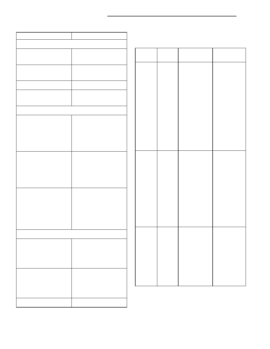
OVERSIZE AND UNDERSIZE ENGINE

COMPONENT MARKINGS CHART

U/S-O/S

Item

Identification

Identification

Location

U/S

Rod/

R or M R-1-4

ect.

Milled flat on

No.8

.0254

mm

Main

(indicating No.

1

crankshaft

(0.001

in.)

Journal

and 4

connecting

counterweight.

rod journal)

and/or

M-2-3 ect.

(indicating No.

2

and 3 main

bearing
journal)

O/S

Hydraulic

L

Diamond-

shaped

.2032

mm

Tappets

stamp top pad

-

(.008 in.)

front of engine

and flat

ground

on outside

surface of

each

O/S tappet

bore.

O/S

Valve

X

Milled pad

.127 mm

Stems

adjacent to

two

(.005 in.)

tapped holes

(3/8 in.) on

each

end of

cylinder

head.

9a - 66

ENGINE 5.2L INTERNATIONAL

R1

ENGINE 5.2L INTERNATIONAL (Continued)

SPECIAL TOOLS

5.2L ENGINE

Oil Pressure Gauge C-3292

Engine Support Fixture C-3487–A

Valve Spring Compressor MD-998772–A

Adaptor 6633

Adaptor 6716A

Valve Guide Sleeve C-3973

Dial Indicator C-3339

Puller C-3688

Front Oil Seal Installer 6635

Cam Bearing Remover/Installer C3132–A

R1

ENGINE 5.2L INTERNATIONAL

9a - 67

ENGINE 5.2L INTERNATIONAL (Continued)

CYLINDER HEAD

DESCRIPTION

The cast iron cylinder heads (Fig. 3) are mounted

to the cylinder block using ten bolts. The spark plugs
are located in the peak of the wedge between the
valves.

OPERATION

The cylinder head closes the combustion chamber

allowing the pistons to compress the air fuel mixture
to the correct ratio for ignition. The valves located in
the cylinder head open and close either to allow clean
air into the combustion chamber or to allow the
exhaust gases out, depending on the stroke of the
engine.

REMOVAL

(1) Disconnect the battery negative cable.
(2) Drain cooling system (Refer to 7 - COOLING/

ENGINE - STANDARD PROCEDURE).

Camshaft Holder C-3509

Distributor Bushing Puller C-3052

Distributor Bushing Driver/Burnisher C-3053

Piston Ring Compressor C-385

Crankshaft Main Bearing Remover C-3059

Cylinder Bore Gauge C-119

Fig. 3 Cylinder Head Assembly—V-8 Gas Engines

1 - EXHAUST VALVE
2 - SPARK PLUGS
3 - EXHAUST VALVES
4 - SPARK PLUGS
5 - EXHAUST VALVE
6 - INTAKE VALVES
7 - INTAKE VALVES

9a - 68

ENGINE 5.2L INTERNATIONAL

R1

ENGINE 5.2L INTERNATIONAL (Continued)

(3) Remove

the

intake

manifold-to-generator

bracket support rod. Remove the generator.

(4) Remove closed crankcase ventilation system.
(5) Disconnect the evaporation control system.
(6) Remove the air cleaner assembly and air inlet

hose.

(7) Perform the Fuel System Pressure Release pro-

cedure (Refer to 14 - FUEL SYSTEM/FUEL DELIV-
ERY - STANDARD PROCEDURE).

(8) Disconnect the fuel supply line (Refer to 14 -

FUEL

SYSTEM/FUEL

DELIVERY/QUICK

CON-

NECT FITTING - STANDARD PROCEDURE).

(9) Disconnect

accelerator

linkage

and

if

so

equipped, the speed control and transmission kick-
down cables.

(10) Remove distributor cap and wires.
(11) Disconnect the coil wires.
(12) Disconnect heat indicator sending unit wire.
(13) Disconnect heater hoses and bypass hose.
(14) Remove cylinder head covers and gaskets

(Refer to 9 - ENGINE/CYLINDER HEAD/CYLIN-
DER HEAD COVER(S) - REMOVAL).

(15) Remove

intake

manifold

(Refer

to

9

-

ENGINE/MANIFOLDS/INTAKE

MANIFOLD

-

REMOVAL) and throttle body as an assembly. Dis-
card the flange side gaskets and the front and rear
cross-over gaskets.

(16) Remove exhaust manifolds (Refer to 9 -

ENGINE/MANIFOLDS/EXHAUST

MANIFOLD

-

REMOVAL).

(17) Remove rocker arm assemblies and push rods.

Identify to ensure installation in original locations.

(18) Remove the head bolts from each cylinder

head and remove cylinder heads. Discard the cylin-
der head gasket.

(19) Remove spark plugs.

CLEANING

Clean all surfaces of cylinder block and cylinder

heads.

Clean cylinder block front and rear gasket surfaces

using a suitable solvent.

INSPECTION

Inspect all surfaces with a straightedge if there is

any reason to suspect leakage. If out-of-flatness
exceeds 0.00075 mm/mm (0.00075 inch/inch) times
the span length in inches in any direction, either
replace head or lightly machine the head surface.

FOR EXAMPLE: A 305 mm (12 inch) span is

0.102 mm (0.004 inch) out-of-flat. The allowable out-
of-flat is 305 x 0.00075 (12 x 0.00075) equals 0.23
mm (0.009 inch). This amount of out-of-flat is accept-
able.

The

cylinder

head

surface

finish

should

be

1.78-3.00 microns (70-125 microinches).

INSTALLATION

(1) Position the new cylinder head gaskets onto

the cylinder block.

(2) Position the cylinder heads onto head gaskets

and cylinder block.

(3) Starting at top center, tighten all cylinder head

bolts, in sequence, to 68 N·m (50 ft. lbs.) torque (Fig.
4). Repeat procedure, tighten all cylinder head bolts
to 143 N·m (105 ft. lbs.) torque. Repeat procedure to
confirm that all bolts are at 143 N·m (105 ft. lbs.)
torque.

CAUTION: When tightening the rocker arm bolts,
make sure the piston in that cylinder is NOT at
TDC. Contact between the valves and piston could
occur.

(4) Install push rods and rocker arm assemblies in

their original position. Tighten the bolts to 28 N·m
(21 ft. lbs.) torque.

(5) Install the intake manifold (Refer to 9 -

ENGINE/MANIFOLDS/INTAKE

MANIFOLD

-

INSTALLATION) and throttle body assembly.

(6) Install

exhaust

manifolds

(Refer

to

9

-

ENGINE/MANIFOLDS/EXHAUST

MANIFOLD

-

INSTALLATION). Tighten the bolts and nuts to 34
N·m (25 ft. lbs.) torque.

(7) Adjust spark plugs to specifications. (Refer to 8

- ELECTRICAL/IGNITION CONTROL - SPECIFI-
CATIONS). Install the plugs and tighten to 41 N·m
(30 ft. lbs.) torque.

(8) Install coil wires.
(9) Connect heat indicator sending unit wire.
(10) Connect the heater hoses and bypass hose.
(11) Install distributor cap and wires.
(12) Connect the accelerator linkage and if so

equipped, the speed control and transmission kick-
down cables.

Fig. 4 Cylinder Head Bolt Tightening Sequence

R1

ENGINE 5.2L INTERNATIONAL

9a - 69

CYLINDER HEAD (Continued)


Content   ..  535  536  537  538   ..