Dodge Dakota (R1). Manual - part 518


  Index      Dodge     Dodge Dakota (R1) - service repair manual 2000 year


Search            


Content   ..  516  517  518  519   ..


Dodge Dakota (R1). Manual - part 518


CLEANING

Clean the block and pan gasket surfaces.
Trim or remove excess sealant film in the rear

main cap oil pan gasket groove. DO NOT remove
the sealant inside the rear main cap slots.

If present, trim excess sealant from inside the

engine.

Clean oil pan in solvent and wipe dry with a clean

cloth.

Clean oil screen and pipe thoroughly in clean sol-

vent. Inspect condition of screen.

INSPECTION

Inspect oil drain plug and plug hole for stripped or

damaged threads. Repair as necessary.

Inspect oil pan mounting flange for bends or distor-

tion. Straighten flange, if necessary.

INSTALLATION

2WD

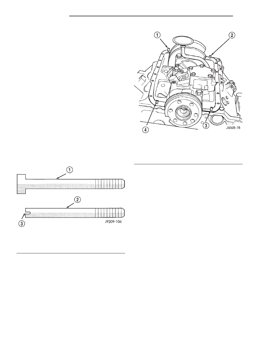
(1) Fabricate 4 alignment dowels from 5/16 x 1 1/2

inch bolts. Cut the head off the bolts and cut a slot
into the top of the dowel. This will allow easier
installation and removal with a screwdriver (Fig. 59).

(2) Install the dowels in the cylinder block (Fig.

60).

(3) Apply small amount of Mopar

t Silicone Rubber

Adhesive Sealant, or equivalent in the corner of the
cap and the cylinder block.

(4) Slide the one-piece gasket over the dowels and

onto the block.

(5) Position the oil pan over the dowels and onto

the gasket.

(6) Install the oil pan bolts. Tighten the bolts to 24

N·m (215 in. lbs.) torque.

(7) Remove the dowels. Install the remaining oil

pan bolts. Tighten these bolts to 24 N·m (215 in. lbs.)
torque.

(8) Install the drain plug. Tighten drain plug to 34

N·m (25 ft. lbs.) torque.

(9) Raise engine by way of oil pan with a wood

block placed between jack and oil pan.

(10) Remove temporary bolts from frame brackets

and lower engine. Install mount insulator through
bolts and tighten to 95 N·m (70 ft. lbs.).

(11) Lower vehicle.
(12) Connect the distributor cap.
(13) Install dipstick.
(14) Connect the negative cable to the battery.
(15) Fill crankcase with oil to proper level.

4WD

(1) Fabricate 4 alignment dowels from 1 1/2 x 5/16

inch bolts. Cut the head off the bolts and cut a slot
into the top of the dowel. This will allow easier
installation and removal with a screwdriver (Fig. 59).

(2) Install the dowels in the cylinder block (Fig.

60).

(3) Apply small amount of Mopar

t Silicone Rubber

Adhesive Sealant, or equivalent in the corner of the
cap and the cylinder block.

(4) Slide the one-piece gasket over the dowels and

onto the block.

(5) Position the oil pan over the dowels and onto

the gasket.

Fig. 59 Fabrication of Alignment Dowels

1 - 1 1/2” x 5/16” BOLT
2 - DOWEL
3 - SLOT

Fig. 60 Position of Dowels in Cylinder Block

1 - DOWEL
2 - DOWEL
3 - DOWEL
4 - DOWEL

9 - 260

ENGINE 5.9L

AN

OIL PAN (Continued)

(6) Install the oil pan bolts. Tighten the bolts to 24

N·m (215 in. lbs.) torque.

(7) Remove the dowels. Install the remaining oil

pan bolts. Tighten these bolts to 24 N·m (215 in. lbs.)
torque.

(8) Install the drain plug. Tighten drain plug to 34

N·m (25 ft. lbs.) torque.

(9) Install transmission inspection cover.
(10) Install engine mount support brackets and

insulators (Refer to 9 - ENGINE/ENGINE MOUNT-
ING/FRONT MOUNT - INSTALLATION).

(11) Install front driving axle (Refer to 3 - DIF-

FERENTIAL & DRIVELINE/FRONT AXLE - C205F
- INSTALLATION).

(12) Lower vehicle
(13) Connect the distributor cap.
(14) Install dipstick.
(15) Connect the negative cable to the battery.
(16) Fill crankcase with oil to proper level.

OIL PUMP

REMOVAL

(1) Remove the oil pan (Refer to 9 - ENGINE/LU-

BRICATION/OIL PAN - REMOVAL).

(2) Remove the oil pump from rear main bearing

cap.

DISASSEMBLY

(1) Remove the relief valve as follows:

(a) Remove cotter pin. Drill a 3.175 mm (1/8

inch) hole into the relief valve retainer cap and
insert a self-threading sheet metal screw.

(b) Clamp screw into a vise and while support-

ing oil pump, remove cap by tapping pump body
using a soft hammer. Discard retainer cap and
remove spring and relief valve (Fig. 61).
(2) Remove oil pump cover (Fig. 62).
(3) Remove pump outer rotor and inner rotor with

shaft (Fig. 62).

(4) Wash all parts in a suitable solvent and inspect

carefully for damage or wear.

INSPECTION

Mating surface of the oil pump cover should be

smooth. Replace pump assembly if cover is scratched
or grooved.

Lay a straightedge across the pump cover surface

(Fig. 63). If a 0.038 mm (0.0015 inch) feeler gauge
can be inserted between cover and straightedge,
pump assembly should be replaced.

Measure thickness and diameter of OUTER rotor.

If outer rotor thickness measures 20.9 mm (0.825
inch) or less or if the diameter is 62.7 mm (2.469
inches) or less, replace outer rotor (Fig. 64).

If inner rotor measures 20.9 mm (0.825 inch) or

less, replace inner rotor and shaft assembly (Fig. 65).

Slide outer rotor into pump body. Press rotor to the

side

with

your

fingers

and

measure

clearance

between rotor and pump body (Fig. 66). If clearance
is 0.356 mm (0.014 inch) or more, replace oil pump
assembly.

Fig. 61 Oil Pressure Relief Valve

1 - OIL PUMP ASSEMBLY
2 - COTTER PIN
3 - RELIEF VALVE
4 - RETAINER CAP
5 - SPRING

Fig. 62 Oil Pump

1 - INNER ROTOR AND SHAFT
2 - BODY
3 - DISTRIBUTOR DRIVESHAFT (REFERENCE)
4 - COTTER PIN
5 - RETAINER CAP
6 - SPRING
7 - RELIEF VALVE
8 - LARGE CHAMFERED EDGE
9 - BOLT
10 - COVER
11 - OUTER ROTOR

AN

ENGINE 5.9L

9 - 261

OIL PAN (Continued)

Install inner rotor and shaft into pump body. If

clearance between inner and outer rotors is 0.203
mm (0.008 inch) or more, replace shaft and both
rotors (Fig. 67).

Fig. 63 Checking Oil Pump Cover Flatness

1 - COVER
2 - STRAIGHT EDGE
3 - FEELER GAUGE

Fig. 64 Measuring Outer Rotor Thickness

Fig. 65 Measuring Inner Rotor Thickness

Fig. 66 Measuring Outer Rotor Clearance in

Housing

1 - PUMP BODY
2 - OUTER ROTOR
3 - FEELER GAUGE

Fig. 67 Measuring Clearance Between Rotors

1 - OUTER ROTOR
2 - FEELER GAUGE
3 - INNER ROTOR

9 - 262

ENGINE 5.9L

AN

OIL PUMP (Continued)

Place a straightedge across the face of the pump,

between bolt holes. If a feeler gauge of 0.102 mm
(0.004 inch) or more can be inserted between rotors
and the straightedge, replace pump assembly (Fig.
68).

Inspect oil pressure relief valve plunger for scoring

and free operation in its bore. Small marks may be
removed with 400-grit wet or dry sandpaper.

The relief valve spring has a free length of approx-

imately 49.5 mm (1.95 inches). The spring should
test between 19.5 and 20.5 pounds when compressed
to 34 mm (1-11/32 inches). Replace spring that fails
to meet these specifications (Fig. 69).

If oil pressure was low and pump is within specifi-

cations, inspect for worn engine bearings or other
reasons for oil pressure loss.

ASSEMBLY

(1) Install pump rotors and shaft, using new parts

as required.

(2) Position the oil pump cover onto the pump

body. Tighten cover bolts to 11 N·m (95 in. lbs.)
torque.

(3) Install the relief valve and spring. Insert the

cotter pin.

(4) Tap on a new retainer cap.
(5) Prime oil pump before installation by filling

rotor cavity with engine oil.

INSTALLATION

(1) Install oil pump. During installation slowly

rotate pump body to ensure driveshaft-to-pump rotor
shaft engagement.

(2) Hold the oil pump base flush against mating

surface on No.5 main bearing cap. Finger tighten
pump attaching bolts. Tighten attaching bolts to 41
N·m (30 ft. lbs.) torque.

(3) Install the oil pan (Refer to 9 - ENGINE/LU-

BRICATION/OIL PAN - INSTALLATION).

EXHAUST MANIFOLD

DESCRIPTION

The exhaust manifolds (Fig. 70) are constructed of

cast iron and are LOG type with balanced flow. One
exhaust manifold is attached to each cylinder head.

OPERATION

The exhaust manifolds collect the engine exhaust

exiting the combustion chambers, then channels the

Fig. 68 Measuring Clearance Over Rotors

1 - STRAIGHT EDGE
2 - FEELER GAUGE

Fig. 69 Proper Installation of Retainer Cap

1 - RETAINER CAP
2 - CHAMFER
3 - COTTER KEY

Fig. 70 Exhaust Manifolds—V-8 Gas Engines Typical

1 - EXHAUST MANIFOLD (LEFT)
2 - BOLTS & WASHERS
3 - NUTS & WASHERS
4 - EXHAUST MANIFOLD (RIGHT)
5 - BOLTS & WASHERS

AN

ENGINE 5.9L

9 - 263

OIL PUMP (Continued)


Content   ..  516  517  518  519   ..