Dodge Dakota (R1). Manual - part 517


  Index      Dodge     Dodge Dakota (R1) - service repair manual 2000 year


Search            


Content   ..  515  516  517  518   ..


Dodge Dakota (R1). Manual - part 517


crankshaft is drilled internally to pass oil from the
main bearing journals to the connecting rod journals.
Each connecting rod bearing has half a hole in it, oil
passes through the hole when the rods rotate and the
hole lines up, oil is then thrown off as the rod
rotates. This oil throwoff lubricates the camshaft
lobes, distributor drive gear, cylinder walls, and pis-
ton pins.

The hydraulic valve tappets receive oil directly

from the main oil gallery. The camshaft bearings
receive oil from the main bearing galleries. The front
camshaft bearing journal passes oil through the cam-
shaft sprocket to the timing chain. Oil drains back to
the oil pan under the No. 1 main bearing cap.

The oil supply for the rocker arms and bridged

pivot assemblies is provided by the hydraulic valve
tappets, which pass oil through hollow push rods to a
hole in the corresponding rocker arm. Oil from the
rocker arm lubricates the valve train components.
The oil then passes down through the push rod guide
holes and the oil drain-back passages in the cylinder

head, past the valve tappet area, and then returns to
the oil pan (Fig. 55).

DIAGNOSIS AND TESTING—ENGINE OIL
LEAKS

Begin with a through visual inspection of the

engine, particularly at the area of the suspected leak.
If an oil leak source is not readily identifiable, the
following steps should be followed:

(1) Do not clean or degrease the engine at this

time because some solvents may cause rubber to
swell, temporarily stopping the leak.

(2) Add an oil-soluble dye (use as recommended by

manufacturer). Start the engine and let idle for
approximately 15 minutes. Check the oil dipstick to
be sure the dye is thoroughly mixed as indicated
with a bright yellow color under a black light source.

(3) Using a black light, inspect the entire engine

for fluorescent dye, particularly at the suspected area
of oil leak. If the oil leak is found and identified,
repair per service manual instructions.

(4) If dye is not observed, drive the vehicle at var-

ious speeds for approximately 24km (15 miles), and
repeat previous step.

(5) If the oil leak source is not positively identified

at this time, proceed with the air leak detection test
method as follows:

(6) Disconnect the breather cap to air cleaner hose

at the breather cap end. Cap or plug breather cap
nipple.

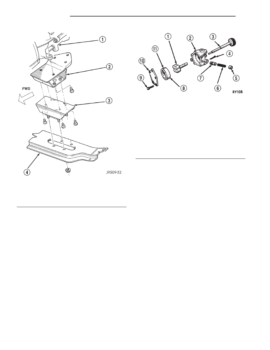
Fig. 53 Rear Insulator—4WD Vehicles

1 - AUTOMATIC TRANSMISSION
2 - INSULATOR BRACKET
3 - INSULATOR
4 - CROSSMEMBER

Fig. 54 Positive Displacement Oil Pump—Typical

1 - INNER ROTOR AND SHAFT
2 - BODY
3 - DISTRIBUTOR DRIVESHAFT (REFERENCE)
4 - COTTER PIN
5 - RETAINER CAP
6 - SPRING
7 - RELIEF VALVE
8 - LARGE CHAMFERED EDGE
9 - BOLT
10 - COVER
11 - OUTER ROTOR

9 - 256

ENGINE 5.9L

AN

LUBRICATION (Continued)

Fig. 55 Oil Lubrication System

1 - OIL DEFLECTOR TAB
2 - BOLT
3 - ROCKER ARM PIVOT
4 - ROCKER ARM
5 - DRIP OILING FOR VALVE TIP
6 - CYLINDER HEAD BOSS
7 - TO MAIN BEARINGS
8 - TO CAMSHAFT BEARINGS
9 - ROCKER ARM
10 - HOLLOW PUSH ROD
11 - TAPPET
12 - TO CONNECTING ROD BEARINGS
13 - OIL INTAKE

14 - OIL PUMP
15 - OIL FILTER
16 - CRANKSHAFT
17 - FROM OIL PUMP
18 - OIL TO FILTER
19 - OIL FROM FILTER TO SYSTEM
20 - PASSAGE TO CAMSHAFT REAR BEARING
21 - RIGHT OIL GALLERY
22 - PLUG
23 - OIL PASSAGE FOR OIL PRESSURE INDICATOR LIGHT
24 - OIL SUPPLY VIA HOLLOW PUSH ROD SUPPLY IS FROM
OIL GALLERY METERED THROUGH HYDRAULIC TAPPET
25 - OIL SUPPLY FROM HOLLOW PUSH ROD

AN

ENGINE 5.9L

9 - 257

LUBRICATION (Continued)

(7) Remove the PCV valve from the cylinder head

cover. Cap or plug the PCV valve grommet.

(8) Attach an air hose with pressure gauge and

regulator to the dipstick tube.

CAUTION: Do not subject the engine assembly to
more than 20.6 kpa (3 PSI) of test pressure.

(9) Gradually apply air pressure from 1 psi to 2.5

psi maximum while applying soapy water at the sus-
pected source. Adjust the regulator to the suitable
test pressure that provide the best bubbles which
will pinpoint the leak source. If the oil leak is
detected and identified, repair per service manual
procedures.

(10) If the leakage occurs at the rear oil seal area,

refer to the section, Inspection for Rear Seal Area
Leak.

(11) If no leaks are detected, turn off the air sup-

ply and remove the air hose and all plugs and caps.
Install the PCV valve and breather cap hose. Proceed
to next step.

(12) Clean the oil off the suspect oil leak area

using a suitable solvent. Drive the vehicle at various
speeds approximately 24 km (15 miles). Inspect the
engine for signs of an oil leak by using a black light.

DIAGNOSIS AND TESTING—ENGINE OIL
PRESSURE

(1) Remove oil pressure sending unit.
(2) Install Oil Pressure Line and Gauge Tool

C-3292. Start engine and record pressure. (Refer to 9
- ENGINE - SPECIFICATIONS).

OIL

STANDARD PROCEDURE - ENGINE OIL

OIL LEVEL INDICATOR (DIPSTICK)

The engine oil level indicator is located at the right

front of the engine, left of the generator (Fig. 56).

CRANKCASE OIL LEVEL INSPECTION

CAUTION: Do not overfill crankcase with engine oil,
oil foaming and oil pressure loss can result.

To ensure proper lubrication of an engine, the

engine oil must be maintained at an acceptable level.
The acceptable levels are indicated between the ADD
and SAFE marks on the engine oil dipstick.

(1) Position vehicle on level surface.
(2) With engine OFF, allow approximately ten min-

utes for oil to settle to bottom of crankcase, remove
engine oil dipstick.

(3) Wipe dipstick clean.

(4) Install dipstick and verify it is seated in the

tube.

(5) Remove dipstick, with handle held above the

tip, take oil level reading.

(6) Add oil only if level is below the ADD mark on

dipstick.

ENGINE OIL CHANGE

Change engine oil at mileage and time intervals

described in the Maintenance Schedule. This infor-
mation can be found in the owner’s manual.

TO CHANGE ENGINE OIL

Run engine until achieving normal operating tem-

perature.

(1) Position the vehicle on a level surface and turn

engine off.

(2) Hoist vehicle.
(3) Remove oil fill cap.
(4) Place a suitable drain pan under crankcase

drain.

(5) Remove drain plug from crankcase and allow

oil to drain into pan. Inspect drain plug threads for
stretching or other damage. Replace drain plug and
gasket if damaged.

(6) Install drain plug in crankcase.
(7) Change oil filter (Refer to 9 - ENGINE/LUBRI-

CATION/OIL FILTER - REMOVAL).

(8) Lower vehicle and fill crankcase with specified

type (Refer to LUBRICATION & MAINTENANCE/
FLUID TYPES - DESCRIPTION) and amount of
engine oil (Refer to LUBRICATION & MAINTE-
NANCE - SPECIFICATIONS).

Fig. 56 Oil Level Indicator Location

1 - CYLINDER HEAD COVER
2 - ENGINE OIL FILL CAP
3 - DIPSTICK
4 - ENGINE OIL FILTER
5 - FILTER BOSS

9 - 258

ENGINE 5.9L

AN

LUBRICATION (Continued)

(9) Install oil fill cap.
(10) Start engine and inspect for leaks.
(11) Stop engine and inspect oil level.

OIL FILTER

REMOVAL

All engines are equipped with a high quality full-

flow, disposable type oil filter. DaimlerChrysler Cor-
poration recommends a Mopar

t or equivalent oil

filter be used.

(1) Position a drain pan under the oil filter.
(2) Using a suitable oil filter wrench loosen filter.
(3) Rotate the oil filter counterclockwise to remove

it from the cylinder block oil filter boss (Fig. 57).

(4) When filter separates from adapter nipple, tip

gasket end upward to minimize oil spill. Remove fil-
ter from vehicle.

(5) With a wiping cloth, clean the gasket sealing

surface (Fig. 70) of oil and grime.

(6) Install new filter (Refer to 9 - ENGINE/LUBRI-

CATION/OIL FILTER - INSTALLATION).

INSTALLATION

(1) Lightly lubricate oil filter gasket with engine

oil or chassis grease.

(2) Thread filter onto adapter nipple. When gasket

makes contact with sealing surface, (Fig. 58) hand
tighten filter one full turn, do not over tighten.

(3) Add oil (Refer to 9 - ENGINE/LUBRICATION/

OIL - STANDARD PROCEDURE).

OIL PAN

REMOVAL

2WD

(1) Disconnect the negative cable from the battery.
(2) Remove engine oil dipstick.
(3) Disconnect distributor cap and position away

from cowl.

(4) Raise vehicle.
(5) Drain engine oil.
(6) Remove engine mount insulator through bolts.
(7) Raise engine by way of oil pan using a block of

wood between the jack and oil pan.

(8) When engine is high enough, place mount

through bolts in the engine mount attaching points
on the frame brackets.

(9) Lower engine so bottom of engine mounts rest

on the replacement bolts placed in the engine mount
frame brackets.

(10) Remove oil pan and one-piece gasket.

4WD

(1) Disconnect the negative cable from the battery.
(2) Remove engine oil dipstick.
(3) Raise vehicle.
(4) Drain engine oil.
(5) Remove front driving axle (Refer to 3 - DIF-

FERENTIAL & DRIVELINE/FRONT AXLE - C205F
- REMOVAL).

(6) Remove both engine mount support brackets

(Refer to 9 - ENGINE/ENGINE MOUNTING/FRONT
MOUNT - REMOVAL).

(7) Remove transmission inspection cover.
(8) Remove oil pan and one-piece gasket.

Fig. 57 Oil Filter Removal—Typical

1 - ENGINE OIL FILTER
2 - OIL FILTER WRENCH

Fig. 58 Oil Filter Sealing Surface—Typical

1 - SEALING SURFACE
2 - RUBBER GASKET
3 - OIL FILTER

AN

ENGINE 5.9L

9 - 259

OIL (Continued)


Content   ..  515  516  517  518   ..