Dodge Dakota (R1). Manual - part 498


  Index      Dodge     Dodge Dakota (R1) - service repair manual 2000 year


Search            


Content   ..  496  497  498  499   ..


Dodge Dakota (R1). Manual - part 498


INSTALLATION

CAUTION: The structural cover must be installed as
described in the following steps. Failure to do so
will cause severe damage to the cover.

(1) Position the structural cover in the vehicle.
(2) Install all four bolts retaining the cover-to-en-

gine. DO NOT tighten the bolts at this time.

(3) Install the four cover-to-transmission bolts. Do

NOT tighten at this time.

CAUTION: The structural cover must be held tightly
against both the engine and the transmission bell
housing during tightening sequence. Failure to do
so may cause damage to the cover.

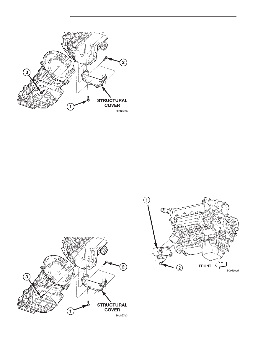
(4) Starting with the two rear cover-to-engine

bolts, tighten bolts (1) (Fig. 87) to 54 N·m (40 ft. lbs.),
then tighten bolts (2) (Fig. 87) and (3) to 54 N·m ( 40
ft. lbs.) in the sequence shown.

(5) Install the exhaust pipe on left hand exhaust

manifold.

(6) Tighten

exhaust

manifold-to-exhaust

pipe

retaining bolts to 20–26 N·m (15–20 ft. lbs.).

FRONT MOUNT

REMOVAL

(1) Disconnect the negative cable from the battery.

CAUTION: Remove the fan blade, fan clutch and fan
shroud before raising engine. Failure to do so may
cause damage to the fan blade, fan clutch and fan
shroud.

(2) Remove the fan blade, fan clutch and fan

shroud (Refer to 7 - COOLING/ENGINE/FAN DRIVE
VISCOUS CLUTCH - REMOVAL).

(3) Remove the engine oil filter.
(4) Support the engine with a suitable jack and a

block of wood across the full width of the engine oil
pan.

(5) Remove the four (4) cylinder block-to-insulator

mount bolts and the nut from the engine insulator
mount through bolt (4x2 Vehicles only) (Fig. 88) (Fig.
89).

(6) Remove the three (3) cylinder block-to-insulator

mount bolts and loosen the nut from the engine insu-
lator mount through bolt (4x4 Vehicles only) (Fig. 90)
(Fig. 91).

Fig. 86 Structural Cover

Fig. 87 Structural Cover

Fig. 88 Engine Insulator Mount 4x2 Vehicle—Left

Side

1 - ENGINE INSULATOR MOUNT-LEFT SIDE
2 - MOUNTING BOLT

9 - 180

ENGINE 4.7L

AN

STRUCTURAL COVER (Continued)

(7) Using the jack, raise the engine high enough to

remove the engine insulator mount through bolt and
the insulator mount.

INSTALLATION

(1) Position the insulator mount and install the

insulator mount through bolt.

(2) Lower the engine until the four cylinder block-

to-insulator mount bolts can be installed.

(3) Remove the jack and block of wood.
(4) Torque the cylinder block-to-insulator mount

bolts to 61N·m ( 45 ft. lbs.).

(5) Install and torque the through bolt retaining

nut to 61N·m (45 ft. lbs.).

(6) Install the fan blade, fan clutch and fan

shroud.

REAR MOUNT

REMOVAL

(1) Raise vehicle on hoist.
(2) Using a suitable jack, support transmission.
(3) Remove the nut from the insulator mount

through bolt (Manual transmission and 4x2 auto-
matic transmission only) (Fig. 92) (Fig. 93).

(4) Remove the four bolts and washers retaining

the mount to the transmission (4x4 automatic trans-
mission only) (Fig. 94).

(5) Raise the transmission enough to remove the

through bolt (Manual transmission and 4x2 auto-
matic transmission only) (Fig. 92) (Fig. 93).

(6) Raise the transmission and remove the bolts

retaining the mount to the crossmember (4x4 auto-
matic transmission only) (Fig. 94).

Fig. 89 Engine Insulator Mount 4x2 Vehicle—Right

Side

1 - ENGINE INSULATOR MOUNT-RIGHT SIDE
2 - MOUNTING BOLT

Fig. 90 Engine Insulator Mount 4x4 Vehicle—Left

Side

1 - ENGINE INSULATOR MOUNT-LEFT SIDE
2 - MOUNTING BOLT

Fig. 91 Engine Insulator Mount 4x4 Vehicle—Right

Side

1 - ENGINE INSULATOR MOUNT-RIGHT SIDE
2 - MOUNTING BOLT

AN

ENGINE 4.7L

9 - 181

FRONT MOUNT (Continued)

(7) Remove the two nuts retaining the isolator to

the crossmember (Manual transmission and 4x2
automatic transmission only) (Fig. 92) (Fig. 93).

(8) Remove the bolts (two bolts manual transmis-

sion)(three bolts 4x2 automatic transmission) retain-
ing the insulator bracket to the transmission.

INSTALLATION

(1) Follow the removal procedure in the reverse

order.

(2) Tighten the through bolt retaining nut to 101

N·m (75 ft. lbs.).

(3) Tighten the isolator bracket to transmission

retaining bolts (Manual transmission and 4x2 auto-
matic transmission only) to 68 N·m (50 ft. lbs.).

(4) Tighten the mount bracket to transmission

retaining bolts (4x4 automatic transmission only) to
68 N·m (50 ft. lbs.).

(5) Tighten the isolator mount to crossmember

retaining nuts (Manual transmission and 4x2 auto-
matic transmission only) to 41 N·m (30 ft. lbs.).

(6) Tighten the mount bracket to crossmember

retaining bolts (4x4 automatic transmission only) to
28 N·m (250 in. lbs.).

Fig. 92 Engine Rear Mount—4X2 Automatic

Transmission

1 - ENGINE REAR MOUNT
2 - BOLT
3 - NUT
4 - THROUGH BOLT NUT
5 - TRANSMISSION

Fig. 93 Engine Rear Mount—4X2 and 4X4 Manual

Transmission

1 - THROUGH BOLT
2 - BOLT
3 - INSULATOR SUPPORT
4 - NUT
5 - NUT AND WASHER
6 - INSULATOR BRACKET TO TRANSMISSION

Fig. 94 Engine Rear Mount—4X4 Automatic

Transmission

1 - TRANSMISSION
2 - ENGINE REAR MOUNT
3 - BOLT

9 - 182

ENGINE 4.7L

AN

REAR MOUNT (Continued)

LUBRICATION

DESCRIPTION

The lubrication system (Fig. 95) is a full flow fil-

tration pressure feed type.

OPERATION

Oil from the oil pan is pumped by a gerotor type oil

pump directly mounted to the crankshaft nose. Oil
pressure is controlled by a relief valve mounted
inside the oil pump housing. For lubrication flow
refer to (Fig. 95).

Fig. 95 Engine Oil Lubrication System

1 - LEFT CYLINDER HEAD OIL GALLERY
2 - OIL PRESSURE SENSOR LOCATION
3 - TO LEFT CYLINDER HEAD
4 - OIL FEED TO IDLER SHAFT
5 - OIL PUMP OUTLET TO BLOCK
6 - OIL PUMP

7 - TO CRANKSHAFT MAIN JOURNALS
8 - RIGHT CYLINDER HEAD OIL GALLERY
9 - TO RIGHT CYLINDER HEAD
10 - CYLINDER BLOCK MAIN GALLERY
11 - OIL FEED TO BOTH SECONDARY TENSIONERS

AN

ENGINE 4.7L

9 - 183


Content   ..  496  497  498  499   ..