Dodge Dakota (R1). Manual - part 492


  Index      Dodge     Dodge Dakota (R1) - service repair manual 2000 year


Search            


Content   ..  490  491  492  493   ..


Dodge Dakota (R1). Manual - part 492


CAUTION: DO NOT STAMP OR STRIKE THE CAM-
SHAFT BEARING CAPS. SEVERE DAMAGE WILL
OCCUR TO THE BEARING CAPS.

NOTE: When the camshaft is removed the rocker
arms may slide downward, mark the rocker arms
before removing camshaft.

(10) Remove the camshaft bearing caps and the

camshaft.

INSTALLATION

(1) Lubricate camshaft journals with clean engine

oil.

NOTE: Position the right side camshaft so that the
camshaft sprocket dowel is near the 10 o’clock
position, This will place the camshaft at the neutral
position easing the installation of the camshaft
bearing caps.

(2) Position the camshaft into the cylinder head.
(3) Install the camshaft bearing caps, hand tighten

the retaining bolts.

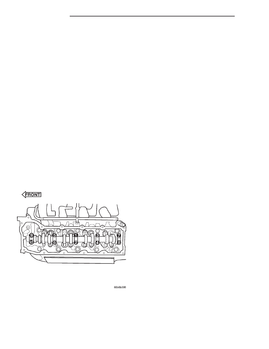
(4) Working in 1/2 turn increments, tighten the

bearing cap retaining bolts starting with the middle
cap working outward (Fig. 38).

(5) Torque the camshaft bearing cap retaining

bolts to 11 N·m (100 in. lbs.).

(6) Position the camshaft drive gear into the tim-

ing chain aligning the V8 mark between the two
marked

chain

links

(Two

links

marked

during

removal) (Fig. 39).

NOTE: When gripping the camshaft, place the pliers
on the tube portion of the camshaft only. Do not
grip the lobes or the sprocket areas.

(7) Using the adjustable pliers, rotate the cam-

shaft until the camshaft sprocket dowel is aligned
with the slot in the camshaft sprocket . Install the
sprocket onto the camshaft (Fig. 40).

CAUTION:

Remove

excess

oil

from

camshaft

sprocket bolt. Failure to do so can cause bolt over-
torque resulting in bolt failure.

(8) Remove excess oil from camshaft sprocket bolt,

then install the camshaft sprocket retaining bolt and
hand tighten.

(9) Remove timing chain wedge special tool 8350

(Fig. 35).

(10) Using Special Tool 6958 spanner wrench with

adapter pins 8346 (Fig. 41), torque the camshaft
sprocket retaining bolt to 122 N·m (90 ft. lbs.).

(11) Install the camshaft position sensor (Fig. 36).
(12) Install the cylinder head cover (Refer to 9 -

ENGINE/CYLINDER

HEAD/CYLINDER

HEAD

COVER(S) - INSTALLATION).

Fig. 38 Camshaft Bearing Caps Tightening

Sequence

9 - 156

ENGINE 4.7L

AN

CAMSHAFT(S) - RIGHT (Continued)

Fig. 39 Timing Chain to Sprocket Alignment

1 - LEFT CYLINDER HEAD
2 - RIGHT CYLINDER HEAD

Fig. 40 Camshaft Sprocket Installation

1 - ADJUSTABLE PLIERS
2 - CAMSHAFT DOWEL

Fig. 41 Tightening Right Side Cam Sprocket

Retaining Bolt

1 - TORQUE WRENCH
2 - SPECIAL TOOL 6958 WITH ADAPTER PINS 8346
3 - LEFT CAMSHAFT SPROCKET
4 - RIGHT CAMSHAFT SPROCKET

AN

ENGINE 4.7L

9 - 157

CAMSHAFT(S) - RIGHT (Continued)

CYLINDER HEAD COVER(S)

DESCRIPTION

The cylinder head covers are made of die cast mag-

nesium, and are not interchangeable from side-to-
side. It is imperative that nothing rest on the
cylinder head covers. Prolonged contact with other
items may wear a hole in the cylinder head cover.

REMOVAL - RIGHT SIDE

(1) Disconnect battery negative cable.
(2) Remove air cleaner assembly, resonator assem-

bly and air inlet hose.

(3) Drain cooling system (Refer to 7 - COOLING -

STANDARD PROCEDURE).

(4) Remove accessory drive belt (Refer to 7 -

COOLING/ACCESSORY

DRIVE/DRIVE

BELTS

-

REMOVAL).

(5) Remove air conditioning compressor retaining

bolts and move compressor to the left.

(6) Remove heater hoses.
(7) Disconnect injector and ignition coil connectors.
(8) Disconnect and remove positive crankcase ven-

tilation (PCV) hose.

(9) Remove oil fill tube.
(10) Un-clip injector and ignition coil harness and

move away from cylinder head cover.

(11) Remove right rear breather tube and filter

assembly.

(12) Remove cylinder head cover retaining bolts.
(13) Remove cylinder head cover.

NOTE: The gasket may be used again, provided no
cuts, tears, or deformation has occurred.

REMOVAL - LEFT SIDE

(1) Disconnect negative cable from battery.
(2) Remove the resonator assemble and air inlet

hose.

(3) Disconnect injector connectors and un-clip the

injector harness.

(4) Route injector harness in front of cylinder head

cover.

(5) Disconnect the left side breather tube and

remove the breather tube.

(6) Remove the cylinder head cover mounting

bolts.

(7) Remove cylinder head cover and gasket.

NOTE: The gasket may be used again, provided no
cuts, tears, or deformation has occurred.

CLEANING

Clean cylinder head cover gasket surface.
Clean head rail, if necessary.

INSTALLATION - RIGHT SIDE

CAUTION: Do not use harsh cleaners to clean the
cylinder head covers. Severe damage to covers
may occur.

CAUTION: DO NOT allow other components includ-
ing the wire harness to rest on or against the
engine cylinder head cover. Prolonged contact with
other objects may wear a hole in the cylinder head
cover.

(1) Clean cylinder head cover and both sealing sur-

faces. Inspect and replace gasket as necessary.

(2) Install cylinder head cover and hand start all

fasteners. Verify that all double ended studs are in
the correct location shown in (Fig. 42).

(3) Tighten cylinder head cover bolts and double

ended studs to 12 N·m (105 in. lbs).

(4) Install right rear breather tube and filter

assembly.

(5) Connect injector, ignition coil electrical connec-

tors and harness retaining clips.

(6) Install the oil fill tube.
(7) Install PCV hose.
(8) Install heater hoses.
(9) Install air conditioning compressor retaining

bolts.

(10) Install accessory drive belt (Refer to 7 -

COOLING/ACCESSORY

DRIVE/DRIVE

BELTS

-

INSTALLATION).

(11) Fill Cooling system (Refer to 7 - COOLING -

STANDARD PROCEDURE).

Fig. 42 Cylinder Head Cover—Right

ITEM

DESCRIPTION

TORQUE

1

Cover Fasteners

12 N·m (105 in. lbs.)

9 - 158

ENGINE 4.7L

AN

(12) Install air cleaner assembly, resonator assem-

bly and air inlet hose.

(13) Connect battery negative cable.

INSTALLATION—LEFT SIDE

CAUTION: Do not use harsh cleaners to clean the
cylinder head covers. Severe damage to covers
may occur.

CAUTION: DO NOT allow other components includ-
ing the wire harness to rest on or against the cylin-
der head cover. Prolonged contact with other
objects may wear a hole in the engine cylinder head
cover.

(1) Clean cylinder head cover and both sealing sur-

faces. Inspect and replace gasket as necessary.

(2) Install cylinder head cover and hand start all

fasteners. Verify that all studs are in the correct loca-
tion shown in (Fig. 43).

(3) Tighten cylinder head cover bolts and double

ended studs to 12 N·m (105 in. lbs.).

(4) Install left side breather and connect breather

tube.

(5) Connect injector electrical connectors and injec-

tor harness retaining clips.

(6) Install the resonator and air inlet hose.
(7) Connect negative cable to battery.

INTAKE/EXHAUST VALVES &
SEATS

DESCRIPTION

The valves are made of heat resistant steel and

have chrome plated stems to prevent scuffing. Each
valve is actuated by a roller rocker arm which pivots
on a stationary lash adjuster. All valves use three
bead lock keepers to retain the springs and promote
valve rotation.

STANDARD PROCEDURE—REFACING

NOTE: Valve seats that are worn or burned can be
reworked, provided that correct angle and seat
width are maintained. Otherwise the cylinder head
must be replaced.

NOTE: When refacing valves and valve seats, it is
important that the correct size valve guide pilot be
used for reseating stones. A true and complete sur-
face must be obtained.

(1) Using a suitable dial indicator measure the

center of the valve seat Total run out must not
exceed 0.051 mm (0.002 in).

(2) Apply a small amount of Prussian blue to the

valve seat, insert the valve into the cylinder head,
while applying light pressure on the valve rotate the
valve. Remove the valve and examine the valve face.
If the blue is transferred below the top edge of the
valve face, lower the valve seat using a 15 degree
stone. If the blue is transferred to the bottom edge of
the valve face, raise the valve seat using a 65 degree
stone.

(3) When the seat is properly positioned the width

of the intake seat must be 1.75 – 2.36 mm (0.0689 –
0.0928 in.) and the exhaust seat must be 1.71 – 2.32
mm (0.0673 – 0.0911 in.).

(4) Check the valve spring installed height after

refacing the valve and seat. The installed height for
both intake and exhaust valve springs must not
exceed 41.44 mm (1.6315 in.) .

(5) The valve seat and valve face must maintain a

face angle of 44.5 – 45 degrees angle (Fig. 44).

Fig. 43 Cylinder Head Cover—Left

ITEM

DESCRIPTION

TORQUE

1

Cover Fasteners

12 N·m (105 in. lbs.)

AN

ENGINE 4.7L

9 - 159

CYLINDER HEAD COVER(S) (Continued)


Content   ..  490  491  492  493   ..