Dodge Dakota (R1). Manual - part 486


  Index      Dodge     Dodge Dakota (R1) - service repair manual 2000 year


Search            


Content   ..  484  485  486  487   ..


Dodge Dakota (R1). Manual - part 486


(8) Disconnect two ground straps from the lower

left hand side and one ground strap from the lower
right hand side of the engine.

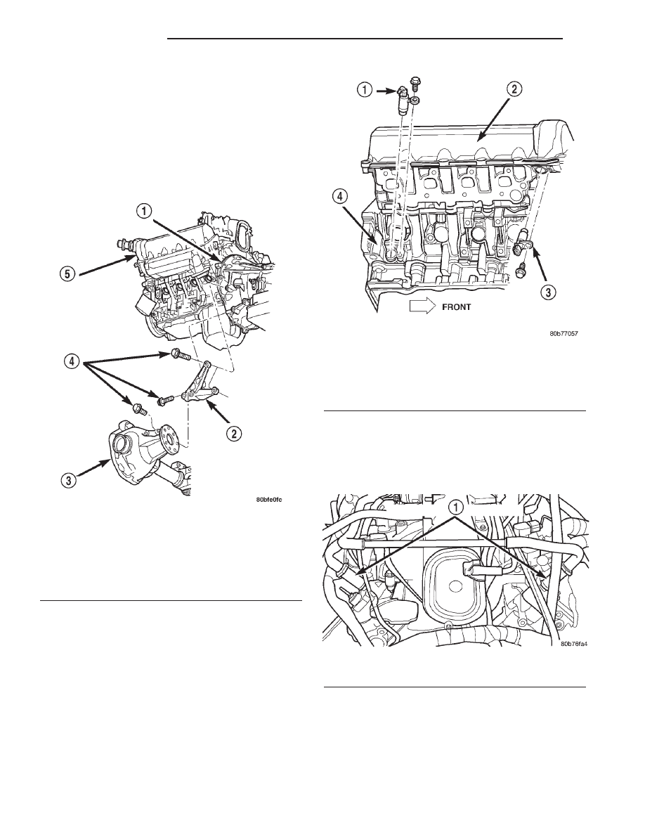
(9) Disconnect crankshaft position sensor. (Fig. 4)

NOTE: The following step applies to 4X4 vehicles
equipped with automatic transmission only.

(10) 4X4 vehiclesRemove the axle isolator bracket

from the engine, transmission and the axle (Fig. 3).

(11) Remove

structural

cover

(Refer

to

9

-

ENGINE/ENGINE BLOCK/STRUCTURAL COVER -
REMOVAL).

(12) Remove starter (Refer to 8 - ELECTRICAL/

STARTING/STARTER MOTOR - REMOVAL).

(13) Drain cooling system (Refer to 7 - COOLING -

STANDARD PROCEDURE).

(14) Remove torque converter bolts (Automatic

Transmission Only).

(15) Remove

transmission

to

engine

mounting

bolts.

(16) Disconnect the engine block heater power

cable from the block heater, if equipped.

(17) Lower vehicle.

(18) Remove throttle body resonator assembly and

air inlet hose.

(19) Disconnect throttle and speed control cables.
(20) Disconnect tube from both the left and right

side crankcase breathers (Fig. 5). Remove breathers

(21) Discharge A/C system (Refer to 24 - HEAT-

ING & AIR CONDITIONING/PLUMBING/REFRIG-
ERANT - STANDARD PROCEDURE).

(22) Remove A/C compressor (Refer to 24 - HEAT-

ING & AIR CONDITIONING/PLUMBING/A/C COM-
PRESSOR - REMOVAL).

Fig. 3 Axle Isolator Bracket Removal / Installation—

4X4 Vehicles With

1 - TRANSMISSION
2 - AXLE ISOLATOR BRACKET
3 - FRONT AXLE 4X4 VEHICLES
4 - BOLTS
5 - ENGINE

Fig. 4 Crankshaft Position Sensor

1 - CRANKSHAFT POSITION SENSOR
2 - CYLINDER HEAD COVER
3 - CAMSHAFT POSITION SENSOR
4 - RIGHT SIDE CYLINDER BLOCK

Fig. 5 Crankcase Breather Connection Points

1 - CRANKCASE BREATHERS

9 - 132

ENGINE 4.7L

AN

ENGINE 4.7L (Continued)

(23) Remove shroud, fan assembly (Refer to 7 -

COOLING/ENGINE/FAN

DRIVE

VISCOUS

CLUTCH - REMOVAL) and accessory drive belt
(Refer to 7 - COOLING/ACCESSORY DRIVE/DRIVE
BELTS - REMOVAL).

(24) Disconnect transmission oil cooler lines at the

radiator.

(25) Disconnect radiator upper and lower hoses.
(26) Remove radiator (Refer to 7 - COOLING/EN-

GINE/RADIATOR

-

REMOVAL),

A/C

condenser

(Refer to 24 - HEATING & AIR CONDITIONING/
PLUMBING/A/C CONDENSER - REMOVAL) and
transmission oil cooler.

(27) Remove generator (Refer to 8 - ELECTRICAL/

CHARGING/GENERATOR - REMOVAL).

(28) Disconnect the two heater hoses from the tim-

ing chain cover and heater core.

(29) Unclip and remove heater hoses and tubes

from the intake manifold (Fig. 6).

(30) Disconnect engine harness at the following

points :

• Intake air temperature (IAT) sensor (Fig. 7)

• Fuel Injectors

• Throttle Position (TPS) Switch

• Idle Air Control (IAC) Motor

• Engine Oil Pressure Switch

• Engine Coolant Temperature (ECT) Sensor

• Manifold absolute pressure (MAP) Sensor

• Camshaft Position (CMP) Sensor

• Coil Over Plugs

(31) Disconnect the vacuum lines at the throttle

body and intake manifold.

(32) Release fuel rail pressure (Refer to 14 - FUEL

SYSTEM/FUEL DELIVERY - STANDARD PROCE-
DURE) then disconnect the fuel supply quick connect
fitting at the fuel rail (Refer to 14 - FUEL SYSTEM/
FUEL DELIVERY/QUICK CONNECT FITTING -
STANDARD PROCEDURE).

(33) Remove power steering pump and position out

of the way.

(34) Install Special Tools 8400 Lifting Studs, into

the cylinder heads.

(35) Install Engine Lifting Fixture Special Tool

8347 (Fig. 8) following these steps.

• Holding the lifting fixture at a slight angle, slide

the large bore in the front plate over the hex portion
of the lifting stud.

• Position the two remaining fixture arms onto

the two Special Tools 8400 Lifting Studs, in the cyl-
inder heads.

Fig. 6 Heater Hoses and Tubes Removal /

Installation

1 - HEATER HOSES AND TUBES
2 - ROUTING/RETAINING CLIPS

Fig. 7 Throttle Body Connection Points

1 - THROTTLE BODY
2 - TPS
3 - IAC MOTOR
4 - IAT SENSOR
5 - MOUNTING SCREWS

AN

ENGINE 4.7L

9 - 133

ENGINE 4.7L (Continued)

• Pull foward and upward on the lifting fixture so

that the lifting stud rest in the slotted area below the
large bore.

• Secure the lifting fixture to the three studs

using three 7/16 – 14 N/C locknuts.

• Make sure the lifting loop in the lifting fixture is

in the last hole (closest to the throttle body) to min-
imize the angle of engine during removal.

(36) Disconnect body ground strap at the right side

cowl (Fig. 9).

(37) Disconnect body ground strap at the left side

cowl (Fig. 10).

NOTE: It will be necessary to support the transmis-
sion in order to remove the engine.

(38) Position a suitable jack under the transmis-

sion.

(39) Remove engine from the vehicle.

Fig. 8 Engine Lifting Fixture Attachment Locations

1 - ATTACHING LOCATION
2 - ADJUSTABLE HOOK
3 - SPECIAL TOOL 8347 ENGINE LIFT FIXTURE
4 - ATTACHING LOCATIONS

Fig. 9 Body Ground Strap—Right Side Removal /

Installation

1 - NUT
2 - A/C ACCUMULATOR
3 - GROUND STRAP

Fig. 10 Body Ground Strap—Left Side Removal /

Installation

1 - NUT
2 - GROUND STRAP
3 - BRAKE BOOSTER

9 - 134

ENGINE 4.7L

AN

ENGINE 4.7L (Continued)

INSTALLATION

(1) Position engine in the vehicle.
Position both the left and right side engine mount

brackets and install the through bolts and nuts.
Tighten nuts to 4X2 vehicles 95 N·m (70 ft. lbs.).
4X4 vehicles 102 N·m (75 ft. lbs.).

(2) 4X4 vehicles Install locknuts onto the engine

mount brackets. Tighten locknuts to 41 N·m (30 ft.
lbs.).

(3) Remove jack from under the transmission.
(4) Remove Engine Lifting Fixture Special Tool

8347 (Fig. 8).

(5) Remove Special Tools 8400 Lifting Studs.
(6) Position generator wiring behind the oil dip-

stick tube, then install the oil dipstick tube upper
mounting bolt.

(7) Connect both left and right side body ground

straps.

(8) Install power steering pump.
(9) Connect fuel supply line quick connect fitting

(Refer to 14 - FUEL SYSTEM/FUEL DELIVERY/
QUICK CONNECT FITTING - STANDARD PROCE-
DURE).

(10) Connect the vacuum lines at the throttle body

and intake manifold.

(11) Connect

engine

harness

at

the

following

points (Fig. 7):

• Intake Air Temperature (IAT) Sensor

• Idle Air Control (IAC) Motor

• Fuel Injectors

• Throttle Position (TPS) Switch

• Engine Oil Pressure Switch

• Engine Coolant Temperature (ECT) Sensor

• Manifold Absolute Pressure (MAP) Sensor

• Camshaft Position (CMP) Sensor

• Coil Over Plugs
(12) Position and install heater hoses and tubes

onto intake manifold.

(13) Install the heater hoses onto the heater core

and the engine front cover.

(14) Install generator (Refer to 8 - ELECTRICAL/

CHARGING/GENERATOR - INSTALLATION).

(15) Install A/C condenser (Refer to 24 - HEATING

&

AIR

CONDITIONING/PLUMBING/A/C

CON-

DENSER - INSTALLATION), radiator (Refer to 7 -
COOLING/ENGINE/RADIATOR - INSTALLATION)
and transmission oil cooler.

(16) Connect radiator upper and lower hoses.
(17) Connect the transmission oil cooler lines to

the radiator.

(18) Install accessory drive belt (Refer to 7 -

COOLING/ACCESSORY

DRIVE/DRIVE

BELTS

-

INSTALLATION), fan assembly and shroud (Refer to
7

-

COOLING/ENGINE/FAN

DRIVE

VISCOUS

CLUTCH - INSTALLATION).

(19) Install A/C compressor (Refer to 24 - HEAT-

ING & AIR CONDITIONING/PLUMBING/A/C COM-
PRESSOR - INSTALLATION).

(20) Install both breathers. Connect tube to both

crankcase breathers (Fig. 5).

(21) Connect throttle and speed control cables.
(22) Install throttle body resonator assembly and

air inlet hose. Tighten clamps 4 N·m (35 in. lbs.).

(23) Raise vehicle.
(24) Install transmission to engine mounting bolts.

Tighten the bolts to 41 N·m (30 ft. lbs.).

(25) Install

torque

converter

bolts

(Automatic

Transmission Only).

(26) Connect crankshaft position sensor (Fig. 4).
(27) 4X4 vehicles Position and install the axle

isolator bracket onto the axle, transmission and
engine block. Tighten bolts to specification (Refer to 9
- ENGINE - SPECIFICATIONS).

(28) Install starter (Refer to 8 - ELECTRICAL/

STARTING/STARTER MOTOR - INSTALLATION).

CAUTION: The structural cover requires a specific
torque sequence. Failure to follow this sequence
may cause severe damage to the cover.

(29) Install structural cover (Refer to 9 - ENGINE/

ENGINE BLOCK/STRUCTURAL COVER - INSTAL-
LATION).

(30) Install exhaust crossover pipe.
(31) Install engine block heater power cable, If

equipped.

(32) 4X4 vehicles Connect axle vent tube to left

side engine mount.

(33) Lower vehicle.
(34) Check and fill engine oil.
(35) Recharge the A/C system (Refer to 24 - HEAT-

ING & AIR CONDITIONING/PLUMBING/REFRIG-
ERANT - STANDARD PROCEDURE).

(36) Refill the engine cooling system (Refer to 7 -

COOLING - STANDARD PROCEDURE).

(37) Install the battery tray and battery.
(38) Connect the battery positive and negative

cables.

(39) Start the engine and check for leaks.

AN

ENGINE 4.7L

9 - 135

ENGINE 4.7L (Continued)


Content   ..  484  485  486  487   ..