Dodge Dakota (R1). Manual - part 483
TIMING BELT / CHAIN
COVER(S)
REMOVAL
(1) Disconnect the battery negative cable.
(2) Drain cooling system (Refer to 7 - COOLING -
STANDARD PROCEDURE).
(3) Remove the serpentine belt (Refer to 7 - COOL-
ING/ACCESSORY DRIVE/DRIVE BELTS - REMOV-
AL).
(4) Remove water pump (Refer to 7 - COOLING/
ENGINE/WATER PUMP - REMOVAL).
(5) Remove power steering pump (Refer to 19 -
STEERING/PUMP - REMOVAL).
(6) Remove
vibration
damper
(Refer
to
9
-
ENGINE/ENGINE BLOCK/VIBRATION DAMPER -
REMOVAL).
(7) Loosen oil pan bolts and remove the front bolt
at each side.
(8) Remove the cover bolts.
(9) Remove chain case cover and gasket using
extreme caution to avoid damaging oil pan gasket.
(10) From the inside of the cover tap the front
crankshaft oil seal outward. Be careful not to damage
the timing cover sealing surface.
INSTALLATION
(1) Be sure mating surfaces of chain case cover
and cylinder block are clean and free from burrs.
(2) Using a new cover gasket, carefully install
chain case cover to avoid damaging oil pan gasket.
Use a small amount of Mopar
t GEN II Silicone Rub-
ber Adhesive Sealant, or equivalent, at the joint
between timing chain cover gasket and the oil pan
gasket. Finger tighten the timing chain cover bolts at
this time.
CAUTION: If chain cover is replaced for any reason,
be sure the oil hole (passenger side of cover) is
plugged.
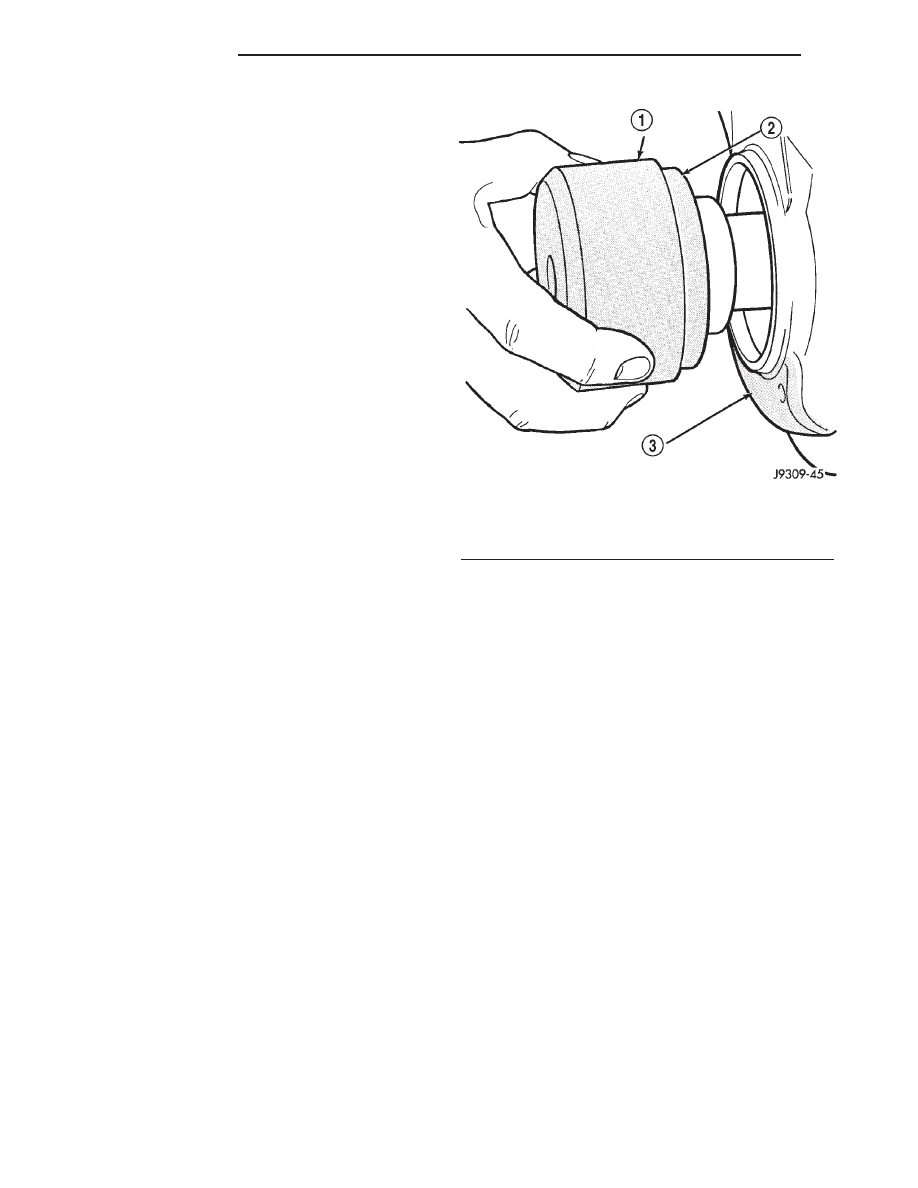
NOTE: Special Tool 6635 must be used to align
cover and seal with crankshaft.
(3) Position the special tool 6635 onto the crank-
shaft (Fig. 82).
(4) Tighten chain case cover bolts to 41 N·m (30 ft.
lbs.) torque. Tighten oil pan bolts to 24 N·m (215 in.
lbs.) torque.
(5) Remove special tool 6635.
(6) Inspect
the
seal
flange
on
the
vibration
damper.
(7) Install vibration damper (Refer to 9 - ENGINE/
ENGINE BLOCK/VIBRATION DAMPER - INSTAL-
LATION).
(8) Install water pump (Refer to 7 - COOLING/EN-
GINE/WATER PUMP - INSTALLATION).
(9) Install power steering pump (Refer to 19 -
STEERING/PUMP - INSTALLATION).
(10) Install the serpentine belt (Refer to 7 - COOL-
ING/ACCESSORY DRIVE/DRIVE BELTS - INSTAL-
LATION).
(11) Install the cooling system fan (Refer to 7 -
COOLING/ENGINE/FAN
DRIVE
VISCOUS
CLUTCH - INSTALLATION).
(12) Position the fan shroud and install the bolts.
Tighten the bolts to 11 N·m (95 in. lbs.) torque.
(13) Fill cooling system (Refer to 7 - COOLING -
STANDARD PROCEDURE).
(14) Connect the negative cable to the battery.
TIMING BELT/CHAIN
TENSIONER AND PULLEY
DESCRIPTION
The timing chain tensioner is a stamped steel con-
stant tension mechanical design. It is mounted to the
front of the engine, behind the timing chain drive.
OPERATION
The timing chain tension is maintained by routing
the timing chain through the tensioner assembly. A
nylon covered spring steel arm presses on the timing
chain maintaining the correct chain tension.
Fig. 82 Position Special Tool 6635 onto Crankshaft
1 - SPECIAL TOOL 6635
2 - OIL SEAL
3 - TIMING CHAIN COVER
9 - 120
ENGINE 3.9L
AN