Dodge Dakota (R1). Manual - part 356


  Index      Dodge     Dodge Dakota (R1) - service repair manual 2000 year


Search            


Content   ..  354  355  356  357   ..


Dodge Dakota (R1). Manual - part 356


(3) If vacuum is less than ten inches of mercury,

determine source of leak. Check vacuum line to
engine for leaks. Also check actual engine intake
manifold vacuum. If manifold vacuum does not meet
this requirement, check for poor engine performance
and repair as necessary.

(4) If vacuum line to engine is not leaking, check

for leak at vacuum reservoir. To locate and gain
access to reservoir, refer to Vacuum Reservoir Remov-
al/Installation in this group. Disconnect vacuum line
at reservoir and connect a hand-operated vacuum
pump to reservoir fitting. Apply vacuum. Reservoir
vacuum should not bleed off. If vacuum is being lost,
replace reservoir.

(5) Verify operation of one-way check valve and

check it for leaks.

(a) Locate one-way check valve. The valve is

located in vacuum line between vacuum reservoir
and engine vacuum source. Disconnect vacuum
hoses (lines) at each end of valve.

(b) Connect a hand-operated vacuum pump to

reservoir end of check valve. Apply vacuum. Vac-
uum should not bleed off. If vacuum is being lost,
replace one-way check valve.

(c) Connect a hand-operated vacuum pump to

vacuum source end of check valve. Apply vacuum.
Vacuum should flow through valve. If vacuum is
not flowing, replace one-way check valve. Seal the
fitting at opposite end of valve with a finger and
apply vacuum. If vacuum will not hold, diaphragm
within check valve has ruptured. Replace valve.

REMOVAL

The vacuum reservoir is located under the plastic

cowl plenum cover at lower base of windshield (Fig.
9) or (Fig. 11).

(1) Disconnect and isolate negative battery at

cable.

(2) Remove

both

windshield

wiper

arm/blade

assemblies. Refer to 8, Wiper and Washer Systems.

(3) Remove rubber weather-strip at front edge of

cowl grill (Fig. 10).

(4) Remove four plastic nuts securing cowl plenum

cover/grille panel to studs on cowl top panel near
base of windshield (Fig. 11).

(5) Remove two plastic rivets securing each side of

the cowl plenum cover/grille panel to cowl plenum
panel and cowl top panel.

(6) Lift cowl plenum cover/grille panel from vehicle

far enough to access windshield washer and vacuum
plumbing near right end of cowl plenum.

(7) Disconnect windshield washer supply hose at

in-line connector.

(8) Disconnect vacuum supply hose from vacuum

supply connector at vacuum reservoir (Fig. 9).

(9) Remove cowl plenum cover/grille panel from

vehicle.

(10) Remove three reservoir mounting screws (Fig.

9).

(11) Remove vacuum reservoir from vehicle.

INSTALLATION

The vacuum reservoir is located under the plastic

cowl plenum cover at lower base of windshield (Fig.
9) or (Fig. 11).

(1) Install vacuum reservoir and three mounting

screws to plastic cowl cover. Tighten three screws to
2.2 N·m (20 in. lbs.) torque.

(2) Position cowl plenum cover/grille panel to vehi-

cle.

(3) Connect vacuum supply hose to vacuum reser-

voir.

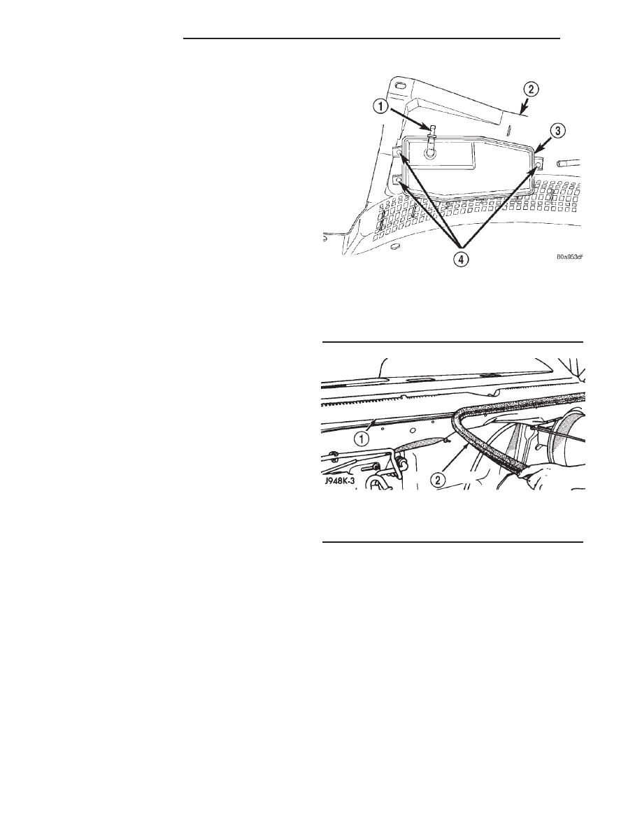
Fig. 9 Vacuum Reservoir Mounting

1 - VACUUM SUPPLY CONNECTOR
2 - COWL PLENUM COVER/GRILLE PANEL
3 - VACUUM RESERVOIR
4 - SCREWS

Fig. 10 Cowl Grille Panel Weather-strip

1 - COWL GRILLE
2 - WEATHERSTRIP

8P - 8

SPEED CONTROL

AN

VACUUM RESERVOIR (Continued)

(4) Connect windshield washer supply hose at in-

line connector.

(5) Install and tighten cowl cover fasteners to vehi-

cle body.

(6) Install rubber weather-strip at front edge of

cowl grill.

(7) Install windshield wiper arms. Refer to 8,

Wiper and Washer Systems.

(8) Connect negative battery to cable.

Fig. 11 Cowl Plenum Cover/Grille Panel Remove/Install

1 - PLASTIC RIVET
2 - IN-LINE WASHER SUPPLY HOSE CONNECTOR
3 - STUD

4 - PLASTIC NUT
5 - COWL PLENUM COVER/GRILLE PANEL

AN

SPEED CONTROL

8P - 9

VACUUM RESERVOIR (Continued)

VEHICLE THEFT SECURITY

TABLE OF CONTENTS

page

page

VEHICLE THEFT SECURITY

DESCRIPTION . . . . . . . . . . . . . . . . . . . . . . . . . . . . 1
OPERATION . . . . . . . . . . . . . . . . . . . . . . . . . . . . . 2
DIAGNOSIS AND TESTING . . . . . . . . . . . . . . . . . . 3

VEHICLE THEFT SECURITY SYSTEM . . . . . . . . 3
SENTRY KEY IMMOBILIZER SYSTEM . . . . . . . . 4

STANDARD PROCEDURE . . . . . . . . . . . . . . . . . . . 6

SKIS INITIALIZATION . . . . . . . . . . . . . . . . . . . . . 6
SENTRY KEY TRANSPONDER
PROGRAMMING. . . . . . . . . . . . . . . . . . . . . . . . . 6

TRANSPONDER KEY

DESCRIPTION . . . . . . . . . . . . . . . . . . . . . . . . . . . . 7
OPERATION . . . . . . . . . . . . . . . . . . . . . . . . . . . . . 8

VEHICLE THEFT SECURITY

DESCRIPTION - VEHICLE THEFT SECURITY
SYSTEM

The Vehicle Theft Security System (VTSS) is an

available factory-installed option on this model. The
VTSS is designed to provide perimeter protection
against unauthorized use or tampering by monitoring
the vehicle doors and the ignition system. If unautho-
rized use or tampering is detected, the system
responds by pulsing the horn and flashing the head-
lamp high beams. If the vehicle is also equipped with
the optional Sentry Key Immobilizer System (SKIS),
which provides passive vehicle protection by prevent-
ing the engine from operating unless a valid electron-
ically encoded key is detected in the ignition lock
cylinder, the VTSS will also disable the engine from
operating until the system is disarmed. (Refer to 8 -
ELECTRICAL/VEHICLE THEFT SECURITY - DESCRIP-
TION - SENTRY KEY IMMOBILIZER SYSTEM).

The VTSS includes the following major compo-

nents, which are described in further detail else-
where in this service information:

• Central Timer Module - The Central Timer

Module (CTM) is located on the left cowl side inner
panel under the driver side outboard end of the
instrument panel. The CTM contains a microproces-
sor and software that allow it to provide the proper
VTSS features and outputs based upon the moni-
tored inputs. The CTM circuitry monitors hard wired
switch inputs, as well as message inputs received
from other vehicle electronic modules on the Pro-
grammable Communications Interface (PCI) data bus
network. (Refer to 8 - ELECTRICAL/ELECTRONIC
CONTROL MODULES/BODY CONTROL/CENTRAL
TIMER MODULE - DESCRIPTION).

• Door Ajar Switch - A door ajar switch is inte-

gral to the latch of each door in the vehicle. These
switches provide an input to the VTSS indicating
whether each door is opened or closed. (Refer to 8 -

ELECTRICAL/LAMPS/LIGHTING

-

INTERIOR/

DOOR AJAR SWITCH - DESCRIPTION).

• Door Cylinder Lock Switch - A door cylinder

lock switch is located on the back of each front door
lock cylinder. This switch provides an input to the
VTSS indicating whether the system should remain
armed or be disarmed. (Refer to 8 - ELECTRICAL/
POWER LOCKS/DOOR CYLINDER LOCK SWITCH
- DESCRIPTION).

• Horn Relay - The horn relay is located in the

Power Distribution Center (PDC) in the engine com-
partment near the battery. The horn relay is nor-
mally activated by the horn switch to control the
sounding of the vehicle horn or horns. However, it
can also be activated by an output of the CTM to pro-
vide an audible indication that unauthorized vehicle
use or tampering has been detected. (Refer to 8 -
ELECTRICAL/HORN/HORN RELAY - DESCRIPTION).

• Security Indicator - A red Light Emitting

Diode (LED) located in the ElectroMechanical Instru-
ment Cluster (EMIC) is illuminated by an output of
the CTM to indicate the status of the VTSS or SKIS.
This LED is integral to the instrument cluster. (Refer
to 8 - ELECTRICAL/INSTRUMENT CLUSTER -
DESCRIPTION).

Hard wired circuitry connects many of the VTSS

components to each other through the electrical sys-
tem of the vehicle. These hard wired circuits are
integral to several wire harnesses, which are routed
throughout the vehicle and retained by many differ-
ent methods. These circuits may be connected to each
other, to the vehicle electrical system and to the
VTSS components through the use of a combination
of soldered splices, splice block connectors, and many
different types of wire harness terminal connectors
and insulators. Refer to the appropriate wiring infor-
mation. The wiring information includes wiring dia-
grams, proper wire and connector repair procedures,
further details on wire harness routing and reten-
tion, as well as pin-out and location views for the
various wire harness connectors, splices and grounds.

AN

VEHICLE THEFT SECURITY

8Q - 1


Content   ..  354  355  356  357   ..