Dodge Dakota (R1). Manual - part 350


  Index      Dodge     Dodge Dakota (R1) - service repair manual 2000 year


Search            


Content   ..  348  349  350  351   ..


Dodge Dakota (R1). Manual - part 350


(2) Route the horn switch ground pigtail wire

through the clearance notch between the two upper
left hooks on the driver airbag housing. Install the
eyelet terminal over the upper left inflator stud and
engage the terminal under the anti-rotation tab
directly above the stud on the back of the driver air-
bag housing.

(3) Install and tighten the nut and washer that

secure the horn switch ground pigtail wire eyelet ter-
minal to the upper left inflator stud on the back of
the driver airbag housing. Tighten the nut to 7 N·m
(65 in. lbs.).

(4) Route the horn switch feed pigtail wire through

the clearance notch between the two upper right
hooks and between the upper right inflator stud and
the inflator on the back of the driver airbag housing.

(5) Using hand pressure, press the plastic wire

retainer onto the upper right inflator stud to capture
the horn switch feed pigtail wire between the stud
and the inflator on the back of the driver airbag
housing.

(6) Carefully position the driver airbag into the

receptacle on the back of the trim cover. Be certain
that the horn switch feed and ground pigtail wires
remain

properly

routed

through

the

clearance

notches at the top of the airbag housing and are not
pinched between the airbag housing and the walls of
the trim cover receptacle.

(7) Work around the perimeter of the unit engag-

ing each of the twelve hooks on the driver airbag
housing through the windows in the walls of the trim
cover receptacle.

(8) After each of the twelve hooks on the driver

airbag housing has been engaged in a window of the
trim cover receptacle, try pulling the trim cover and
the airbag housing away from each other. This action
will fully seat the edges of the windows into the cra-
dles of the hooks.

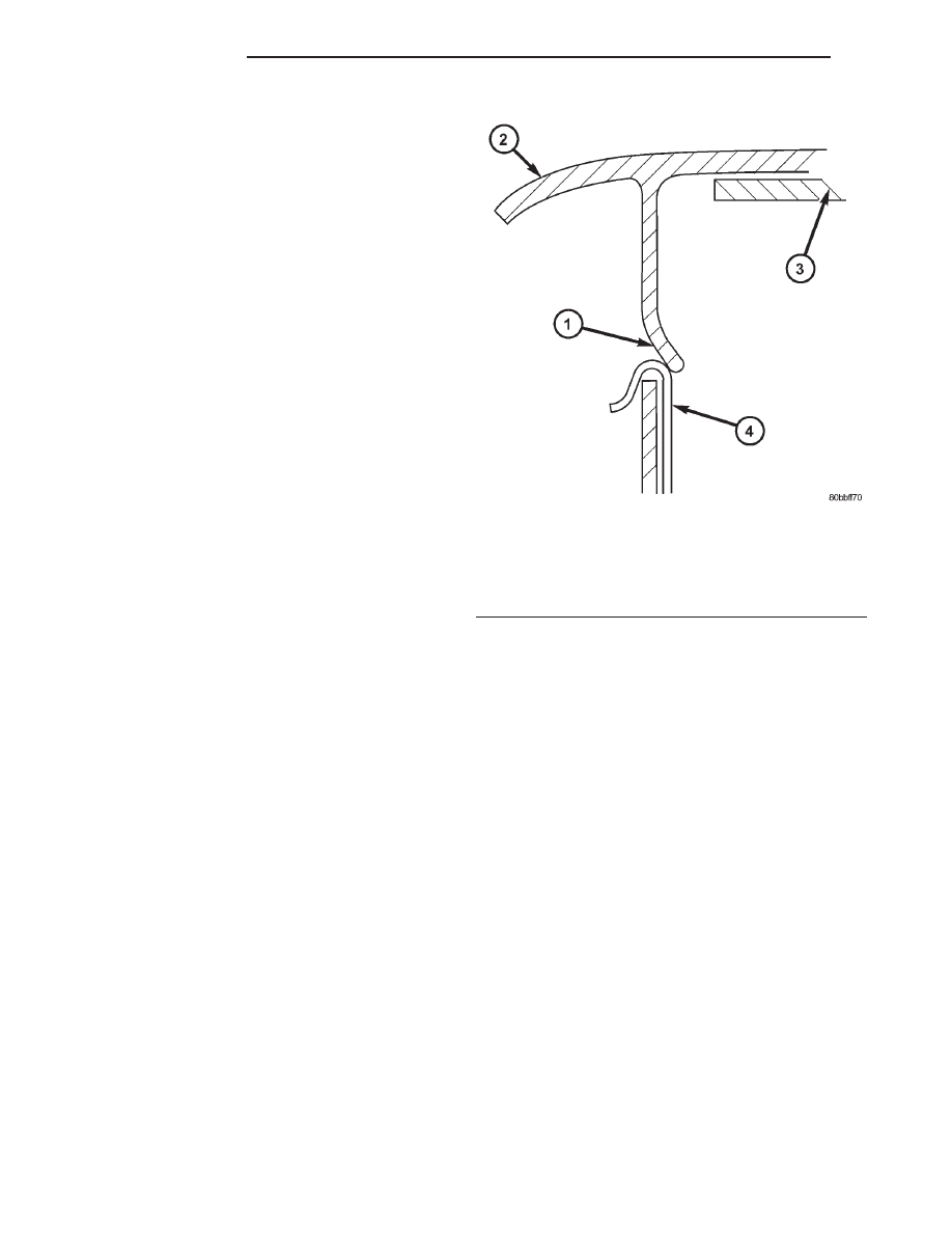
(9) After all of the windows in the walls of the

trim cover receptacle have been fully seated in the
cradles of the hooks on the airbag housing, push the
blocking tabs of the two windows on the right and
left side walls of the trim cover receptacle inward so
that they are oriented behind the airbag housing
hooks, as shown in (Fig. 15).

(10) Inspect the airbag housing hooks in the win-

dows of the upper and lower walls of the trim cover
receptacle to be certain they are fully engaged and
that the blocking tabs for these windows are oriented
over the tops of the hooks, as shown in (Fig. 16).

(11) Reinstall the driver airbag onto the steering

wheel (Refer to 8 - ELECTRICAL/RESTRAINTS/
DRIVER AIRBAG - INSTALLATION).

INSTALLATION

The following procedure is for replacement of a

faulty or damaged driver airbag. If the driver airbag
has been deployed, the clockspring and the steering
column assembly must also be replaced. (Refer to 8 -
ELECTRICAL/RESTRAINTS/CLOCKSPRING

-

REMOVAL) and (Refer to 19 - STEERING/COLUMN
- REMOVAL).

WARNING:

DISABLE

THE

AIRBAG

SYSTEM

BEFORE ATTEMPTING ANY STEERING WHEEL,
STEERING COLUMN, SEAT BELT TENSIONER, OR
INSTRUMENT PANEL COMPONENT DIAGNOSIS OR
SERVICE. DISCONNECT AND ISOLATE THE BAT-
TERY NEGATIVE (GROUND) CABLE, THEN WAIT
TWO MINUTES FOR THE AIRBAG SYSTEM CAPAC-
ITOR TO DISCHARGE BEFORE PERFORMING FUR-
THER DIAGNOSIS OR SERVICE. THIS IS THE ONLY
SURE WAY TO DISABLE THE AIRBAG SYSTEM.
FAILURE TO TAKE THE PROPER PRECAUTIONS
COULD RESULT IN ACCIDENTAL AIRBAG DEPLOY-
MENT AND POSSIBLE PERSONAL INJURY.

Fig. 15 Driver Airbag Trim Cover Side Blocking Tabs

1 - BLOCKING TAB
2 - DRIVER AIRBAG TRIM COVER
3 - HORN SWITCH
4 - AIRBAG HOUSING HOOK

8O - 18

RESTRAINTS

AN

DRIVER AIRBAG (Continued)

WARNING: USE EXTREME CARE TO PREVENT ANY
FOREIGN MATERIAL FROM ENTERING THE DRIVER
AIRBAG, OR BECOMING ENTRAPPED BETWEEN
THE DRIVER AIRBAG CUSHION AND THE DRIVER
AIRBAG TRIM COVER. FAILURE TO OBSERVE THIS
WARNING COULD RESULT IN OCCUPANT INJURIES
UPON AIRBAG DEPLOYMENT.

WARNING: THE DRIVER AIRBAG TRIM COVER
MUST NEVER BE PAINTED. REPLACEMENT TRIM
COVERS ARE SERVICED IN THE ORIGINAL COL-
ORS. PAINT MAY CHANGE THE WAY IN WHICH THE
MATERIAL OF THE TRIM COVER RESPONDS TO AN
AIRBAG DEPLOYMENT. FAILURE TO OBSERVE
THIS WARNING COULD RESULT IN OCCUPANT
INJURIES UPON AIRBAG DEPLOYMENT.

(1) Assemble the driver airbag trim cover onto the

airbag housing. (Refer to 8 - ELECTRICAL/RE-
STRAINTS/DRIVER AIRBAG - ASSEMBLY).

(2) When installing the driver airbag, reconnect

the clockspring driver airbag pigtail wire connector
to the airbag inflator connector receptacle by press-
ing straight in on the connector (Fig. 12). You can be
certain that the connector is fully engaged by listen-
ing carefully for a distinct, audible click as the con-
nector snaps into place.

(3) Reconnect the steering wheel wire harness con-

nector for the horn switch to the horn switch feed
pigtail wire connector, which is located at the back of
the driver airbag.

(4) Carefully position the driver airbag in the

steering wheel. Be certain that the clockspring pig-
tail wire and steering wheel wire harness in the
steering wheel hub area are not pinched between the
driver airbag and the steering wheel armature.

(5) From the underside of the steering wheel,

install and tighten the two screws that secure the
driver

airbag

to

the

steering

wheel

armature.

Tighten the screws to 10 N·m (90 in. lbs.).

(6) Do not reconnect the battery negative cable at

this time. The airbag system verification test proce-
dure should be performed following service of any
airbag system component. (Refer to 8 - ELECTRI-
CAL/RESTRAINTS - STANDARD PROCEDURE -
VERIFICATION TEST).

FRONT SEAT BELT &
RETRACTOR

REMOVAL - QUAD CAB

WARNING: ON VEHICLES EQUIPPED WITH AIR-
BAGS, DISABLE THE AIRBAG SYSTEM BEFORE
ATTEMPTING ANY STEERING WHEEL, STEERING
COLUMN, SEAT BELT TENSIONER, OR INSTRU-
MENT PANEL COMPONENT DIAGNOSIS OR SER-
VICE. DISCONNECT AND ISOLATE THE BATTERY
NEGATIVE (GROUND) CABLE, THEN WAIT TWO
MINUTES FOR THE AIRBAG SYSTEM CAPACITOR
TO DISCHARGE BEFORE PERFORMING FURTHER
DIAGNOSIS OR SERVICE. THIS IS THE ONLY SURE
WAY TO DISABLE THE AIRBAG SYSTEM. FAILURE
TO TAKE THE PROPER PRECAUTIONS COULD
RESULT IN ACCIDENTAL AIRBAG DEPLOYMENT
AND POSSIBLE PERSONAL INJURY.

Fig. 16 Driver Airbag Trim Cover Upper & Lower

Blocking Tabs

1 - BLOCKING TAB
2 - DRIVER AIRBAG TRIM COVER
3 - HORN SWITCH
4 - AIRBAG HOUSING HOOK

AN

RESTRAINTS

8O - 19

DRIVER AIRBAG (Continued)

WARNING: DURING AND FOLLOWING ANY SEAT
BELT SERVICE, CAREFULLY INSPECT ALL SEAT
BELTS, BUCKLES, MOUNTING HARDWARE, AND
RETRACTORS

FOR

PROPER

INSTALLATION,

OPERATION, OR DAMAGE. REPLACE ANY BELT
THAT IS CUT, FRAYED, OR TORN. STRAIGHTEN
ANY

BELT

THAT

IS

TWISTED.

TIGHTEN

ANY

LOOSE FASTENERS. REPLACE ANY BELT THAT
HAS A DAMAGED OR INOPERATIVE BUCKLE OR
RETRACTOR. REPLACE ANY BELT THAT HAS A
BENT OR DAMAGED LATCH PLATE OR ANCHOR
PLATE. NEVER ATTEMPT TO REPAIR A SEAT BELT
COMPONENT. ALWAYS REPLACE DAMAGED OR
FAULTY SEAT BELT COMPONENTS WITH THE COR-
RECT, NEW AND UNUSED REPLACEMENT PARTS
LISTED IN THE MOPAR PARTS CATALOG.

(1) Move the front seats to their most forward

position for easiest access to the lower seat belt
anchor plate, the retractor, and the B-pillar.

(2) Disconnect and isolate the battery negative

cable. If either of the airbags has not been deployed,
wait two minutes for the system capacitor to dis-
charge before further service.

(3) Lift the cover on the lower seat belt anchor

plate far enough to access the screw that secures the
anchor plate to the front seat adjuster.

(4) Remove the screw that secures the lower seat

belt anchor plate to the seat adjuster (Fig. 17).

(5) Unsnap and remove the front shoulder belt

turning loop cover to access the screw that secures
the turning loop to the height adjuster.

(6) Remove the screw that secures the shoulder

belt turning loop to the height adjuster (Fig. 18).

(7) Remove the shoulder belt turning loop from the

height adjuster.

(8) Remove the trim from the B-pillar. (Refer to 23

- BODY/INTERIOR/B-PILLAR TRIM - REMOVAL).

(9) Remove the two screws that secure the seat

belt web guide to the B-pillar above the retractor.

(10) Disconnect the seat belt tensioner pigtail wire

connector from the body wire harness connector.

(11) On the driver side only, disconnect the seat

belt switch pigtail wire connector from the body wire
harness connector.

(12) Remove the screw that secures the retractor

to the B-pillar.

(13) Remove the front shoulder belt and retractor

from the B-pillar.

Fig. 17 Front Seat Belt Lower Anchor

1 - SCREW
2 - SEAT

Fig. 18 Front Shoulder Belt & Retractor - Quad Cab

1 - TURNING LOOP
2 - HEIGHT ADJUSTER
3 - UPPER B-PILLAR TRIM
4 - B-PILLAR
5 - SHIELD
6 - SCREW
7 - LOWER B-PILLAR TRIM
8 - RETRACTOR

8O - 20

RESTRAINTS

AN

FRONT SEAT BELT & RETRACTOR (Continued)

REMOVAL - STANDARD/CLUB CAB

WARNING: DURING AND FOLLOWING ANY SEAT
BELT SERVICE, CAREFULLY INSPECT ALL SEAT
BELTS, BUCKLES, MOUNTING HARDWARE, AND
RETRACTORS

FOR

PROPER

INSTALLATION,

OPERATION, OR DAMAGE. REPLACE ANY BELT
THAT IS CUT, FRAYED, OR TORN. STRAIGHTEN
ANY

BELT

THAT

IS

TWISTED.

TIGHTEN

ANY

LOOSE FASTENERS. REPLACE ANY BELT THAT
HAS A DAMAGED OR INOPERATIVE BUCKLE OR
RETRACTOR. REPLACE ANY BELT THAT HAS A
BENT OR DAMAGED LATCH PLATE OR ANCHOR
PLATE. NEVER ATTEMPT TO REPAIR A SEAT BELT
COMPONENT. ALWAYS REPLACE DAMAGED OR
FAULTY SEAT BELT COMPONENTS WITH THE COR-
RECT, NEW AND UNUSED REPLACEMENT PARTS
LISTED IN THE MOPAR PARTS CATALOG.

(1) Move the front seats to their most forward

position for easiest access to the lower seat belt
anchor plate, the retractor, and the B-pillar.

(2) Disconnect and isolate the battery negative

cable.

(3) Unsnap and remove the front shoulder belt

turning loop cover to access the screw that secures
the turning loop to the height adjuster.

(4) Remove the screw that secures the shoulder

belt turning loop to the height adjuster (Fig. 19).

(5) Remove the shoulder belt turning loop from the

height adjuster.

(6) Remove the trim from the quarter inner panel.

(Refer to 23 - BODY/INTERIOR/QUARTER TRIM
PANEL - REMOVAL).

(7) Remove the screw that secures the lower seat

belt anchor plate to the B-pillar.

(8) Remove the lower seat belt anchor plate from

the B-pillar.

(9) On the driver side only, disconnect the seat belt

switch pigtail wire connector from the body wire har-
ness connector.

(10) Remove the screw that secures the retractor

to the B-pillar.

(11) Remove the front shoulder belt and retractor

from the B-pillar.

INSTALLATION - QUAD CAB

WARNING: ON VEHICLES EQUIPPED WITH AIR-
BAGS, DISABLE THE AIRBAG SYSTEM BEFORE
ATTEMPTING ANY STEERING WHEEL, STEERING
COLUMN, SEAT BELT TENSIONER, OR INSTRU-
MENT PANEL COMPONENT DIAGNOSIS OR SER-
VICE. DISCONNECT AND ISOLATE THE BATTERY
NEGATIVE (GROUND) CABLE, THEN WAIT TWO
MINUTES FOR THE AIRBAG SYSTEM CAPACITOR
TO DISCHARGE BEFORE PERFORMING FURTHER
DIAGNOSIS OR SERVICE. THIS IS THE ONLY SURE
WAY TO DISABLE THE AIRBAG SYSTEM. FAILURE
TO TAKE THE PROPER PRECAUTIONS COULD
RESULT IN ACCIDENTAL AIRBAG DEPLOYMENT
AND POSSIBLE PERSONAL INJURY.

WARNING: DURING AND FOLLOWING ANY SEAT
BELT SERVICE, CAREFULLY INSPECT ALL SEAT
BELTS, BUCKLES, MOUNTING HARDWARE, AND
RETRACTORS

FOR

PROPER

INSTALLATION,

OPERATION, OR DAMAGE. REPLACE ANY BELT
THAT IS CUT, FRAYED, OR TORN. STRAIGHTEN
ANY

BELT

THAT

IS

TWISTED.

TIGHTEN

ANY

LOOSE FASTENERS. REPLACE ANY BELT THAT
HAS A DAMAGED OR INOPERATIVE BUCKLE OR
RETRACTOR. REPLACE ANY BELT THAT HAS A
BENT OR DAMAGED LATCH PLATE OR ANCHOR
PLATE. NEVER ATTEMPT TO REPAIR A SEAT BELT
COMPONENT. ALWAYS REPLACE DAMAGED OR
FAULTY SEAT BELT COMPONENTS WITH THE COR-
RECT, NEW AND UNUSED REPLACEMENT PARTS
LISTED IN THE MOPAR PARTS CATALOG.

(1) Be certain that the retractor shield is properly

installed in the B-pillar and in good condition before
installing the retractor (Fig. 18).

(2) Position the retractor into the B-pillar.

Fig. 19 Front Shoulder Belt & Retractor - Standard/

Club Cab - Typical

1 - TURNING LOOP
2 - QUARTER TRIM
3 - RETRACTOR
4 - LOWER ANCHOR
5 - SEAT BELT SWITCH CONNECTOR (DRIVER SIDE ONLY)
6 - HEIGHT ADJUSTER

AN

RESTRAINTS

8O - 21

FRONT SEAT BELT & RETRACTOR (Continued)


Content   ..  348  349  350  351   ..