Dodge Dakota (R1). Manual - part 349


  Index      Dodge     Dodge Dakota (R1) - service repair manual 2000 year


Search            


Content   ..  347  348  349  350   ..


Dodge Dakota (R1). Manual - part 349


complies with revised federal airbag standards to
deploy with less force than those used in some prior
models. The driver airbag is located in the center of
the steering wheel, where it is secured with two
screws to the steering wheel armature. Concealed
beneath the driver airbag trim cover are the horn
switch, the folded airbag cushion, the airbag retainer
or housing, the airbag inflator, and the retainers that
secure the inflator to the airbag housing. The resis-
tive membrane-type horn switch is secured within a
plastic tray that is inserted in a pocket or pouch
sewn onto the airbag cushion retainer strap, between
the trim cover and the folded airbag cushion (Fig.
11). The airbag inflator is a conventional non-azide,
pyrotechnic-type unit with four studs and it is
secured to the stamped metal airbag housing with
four nuts.

The trim cover has an airbag receptacle molded

into the back side of it. The four vertical walls of this
receptacle have a total of twelve small windows with
blocking tabs that are engaged by twelve hook forma-
tions around the perimeter of the airbag housing.
Each hook is inserted through one of the windows,
the integral blocking tab in each window keeps each
hook properly engaged with the trim cover, locking
the cover securely into place. One horn switch pigtail
wire has an eyelet terminal connector that is cap-
tured beneath a nut and washer on the upper right
inflator mounting stud. The other horn switch pigtail

wire is routed between the upper left inflator mount-
ing stud and the inflator, where it is captured by a
small plastic retainer that is pushed onto the stud.
The driver airbag cannot be repaired, and must be
replaced if deployed or in any way damaged. The
driver airbag trim cover and the horn switch with
tray are available, and may be disassembled from the
driver airbag for service replacement.

OPERATION

The driver airbag is deployed by an electrical sig-

nal generated by the Airbag Control Module (ACM)
through the driver airbag line 1 and line 2 (or squib)
circuits. When the ACM sends the proper electrical
signal to the airbag inflator, the electrical energy
generates enough heat to initiate a small pyrotechnic
charge which, in turn, ignites chemical pellets within
the inflator. Once ignited, these chemical pellets burn
rapidly and produce a large quantity of nitrogen gas.
The inflator is sealed to the back of the airbag hous-
ing and a diffuser in the inflator directs all of the
nitrogen gas into the airbag cushion, causing the
cushion to inflate. As the cushion inflates, the driver
airbag trim cover will split at predetermined break-
out lines, then fold back out of the way along with

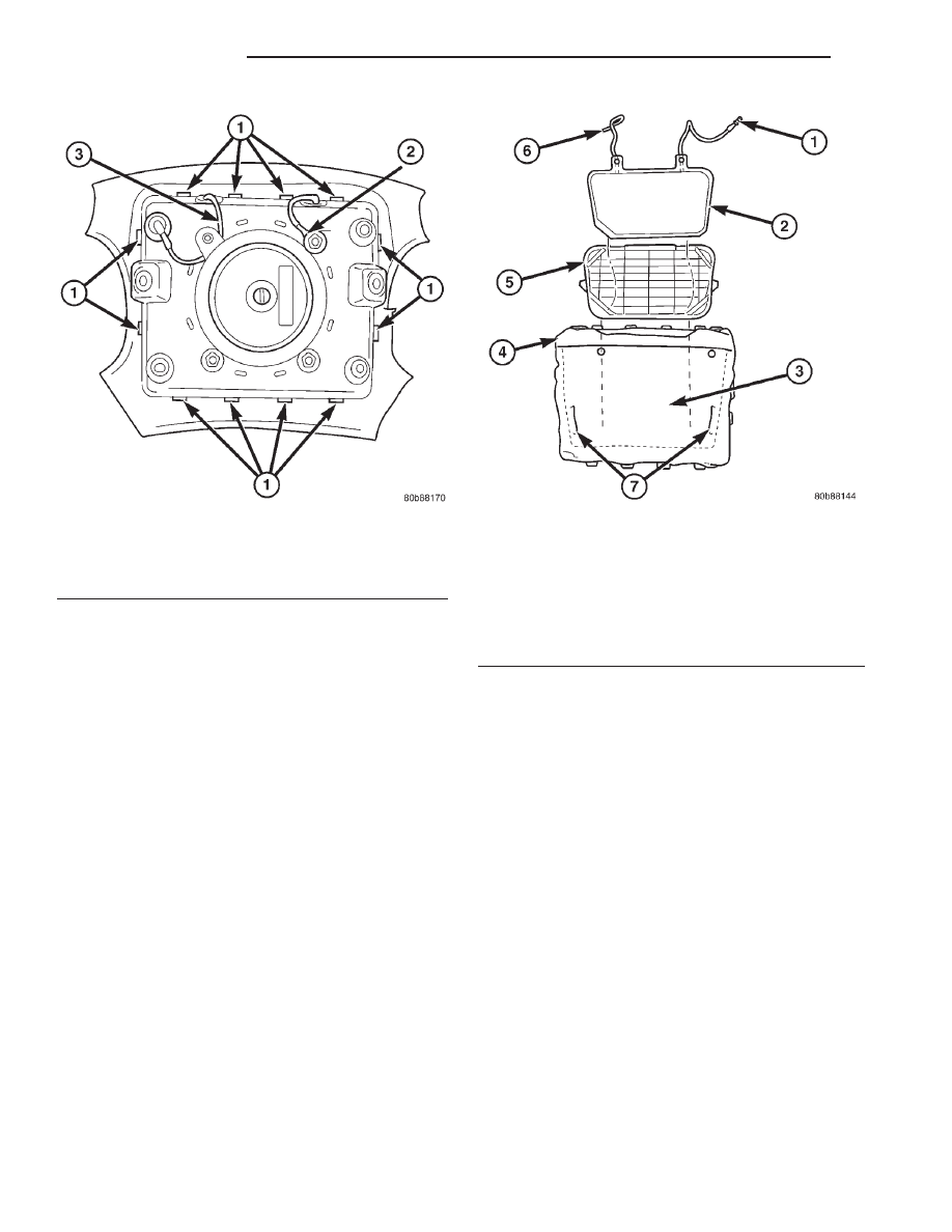
Fig. 10 Driver Airbag

1 - HOUSING HOOKS (12)
2 - HORN SWITCH GROUND PIGTAIL WIRE
3 - HORN SWITCH FEED PIGTAIL WIRE

Fig. 11 Horn Switch

1 - HORN SWITCH GROUND PIGTAIL WIRE
2 - HORN SWITCH
3 - POUCH
4 - DRIVER AIRBAG (TRIM COVER REMOVED)
5 - TRAY
6 - HORN SWITCH FEED PIGTAIL WIRE
7 - POUCH SLITS

8O - 14

RESTRAINTS

AN

DRIVER AIRBAG (Continued)

the horn switch and tray unit. Following an airbag
deployment, the airbag cushion quickly deflates by
venting the nitrogen gas towards the instrument
panel through the porous fabric material used on the
steering wheel side of the airbag cushion.

Some of the chemicals used to create the nitrogen

gas may be considered hazardous in their solid state,
before they are burned, but they are securely sealed
within the airbag inflator. However, the nitrogen gas
that is produced when the chemicals are burned is
harmless. A small amount of residue from the burned
chemicals may cause some temporary discomfort if it
contacts the skin, eyes, or breathing passages. If skin
or eye irritation is noticed, rinse the affected area
with plenty of cool, clean water. If breathing pas-
sages are irritated, move to another area where there
is plenty of clean, fresh air to breath. If the irritation
is not alleviated by these actions, contact a physician.

REMOVAL

The following procedure is for replacement of a

faulty or damaged driver airbag. If the driver airbag
has been deployed, the clockspring and the steering
column assembly must also be replaced. (Refer to 8 -
ELECTRICAL/RESTRAINTS/CLOCKSPRING

-

REMOVAL) (Refer to 19 - STEERING/COLUMN -
REMOVAL).

WARNING:

DISABLE

THE

AIRBAG

SYSTEM

BEFORE ATTEMPTING ANY STEERING WHEEL,
STEERING COLUMN, SEAT BELT TENSIONER, OR
INSTRUMENT PANEL COMPONENT DIAGNOSIS OR
SERVICE. DISCONNECT AND ISOLATE THE BAT-
TERY NEGATIVE (GROUND) CABLE, THEN WAIT
TWO MINUTES FOR THE AIRBAG SYSTEM CAPAC-
ITOR TO DISCHARGE BEFORE PERFORMING FUR-
THER DIAGNOSIS OR SERVICE. THIS IS THE ONLY
SURE WAY TO DISABLE THE AIRBAG SYSTEM.
FAILURE TO TAKE THE PROPER PRECAUTIONS
COULD RESULT IN ACCIDENTAL AIRBAG DEPLOY-
MENT AND POSSIBLE PERSONAL INJURY.

WARNING: WHEN REMOVING A DEPLOYED AIR-
BAG, RUBBER GLOVES, EYE PROTECTION, AND A
LONG-SLEEVED SHIRT SHOULD BE WORN. THERE
MAY BE DEPOSITS ON THE AIRBAG CUSHION AND
OTHER INTERIOR SURFACES. IN LARGE DOSES,
THESE DEPOSITS MAY CAUSE IRRITATION TO THE
SKIN AND EYES.

(1) Disconnect and isolate the battery negative

cable. If either of the airbags has not been deployed,
wait two minutes for the system capacitor to dis-
charge before further service.

(2) From the underside of the steering wheel,

remove the two screws that secure the driver airbag
to the steering wheel armature (Fig. 12).

(3) Pull the driver airbag away from the steering

wheel far enough to access the two wire harness con-
nectors at the back of the airbag.

(4) Disconnect the steering wheel wire harness

connector for the horn switch from the horn switch
feed pigtail wire connector, which is located at the
back of the driver airbag.

CAUTION: Do not pull on the clockspring pigtail
wire to disengage the connector from the driver air-
bag inflator connector receptacle.

(5) The clockspring driver airbag pigtail wire con-

nector is a tight snap-fit into the airbag inflator con-
nector receptacle, which is located at the back of the
driver airbag. Firmly grasp and pull or gently pry on
the clockspring driver airbag wire harness connector
to disconnect it from the airbag inflator connector
receptacle.

(6) Remove the driver airbag from the steering

wheel.

(7) If the driver airbag has been deployed, the

clockspring

and

the

steering

column

must

be

replaced. (Refer to 8 - ELECTRICAL/RESTRAINTS/
CLOCKSPRING - REMOVAL). (Refer to 19 - STEER-
ING/COLUMN - REMOVAL).

DISASSEMBLY

The following procedures can be used to replace

the driver airbag trim cover or the horn switch and
tray unit. If the driver airbag is faulty or deployed,
the entire driver airbag, trim cover, and horn switch
must be replaced as a unit.

WARNING:

DISABLE

THE

AIRBAG

SYSTEM

BEFORE ATTEMPTING ANY STEERING WHEEL,
STEERING COLUMN, SEAT BELT TENSIONER, OR
INSTRUMENT PANEL COMPONENT DIAGNOSIS OR
SERVICE. DISCONNECT AND ISOLATE THE BAT-
TERY NEGATIVE (GROUND) CABLE, THEN WAIT
TWO MINUTES FOR THE AIRBAG SYSTEM CAPAC-
ITOR TO DISCHARGE BEFORE PERFORMING FUR-
THER DIAGNOSIS OR SERVICE. THIS IS THE ONLY
SURE WAY TO DISABLE THE AIRBAG SYSTEM.
FAILURE TO TAKE THE PROPER PRECAUTIONS
COULD RESULT IN ACCIDENTAL AIRBAG DEPLOY-
MENT AND POSSIBLE PERSONAL INJURY.

AN

RESTRAINTS

8O - 15

DRIVER AIRBAG (Continued)

WARNING: THE HORN SWITCH IS INTEGRAL TO
THE DRIVER AIRBAG UNIT. SERVICE OF THIS UNIT
SHOULD BE PERFORMED ONLY BY DAIMLER-
CHRYSLER-TRAINED AND AUTHORIZED DEALER
SERVICE TECHNICIANS. FAILURE TO TAKE THE
PROPER PRECAUTIONS OR TO FOLLOW THE
PROPER PROCEDURES COULD RESULT IN ACCI-
DENTAL, INCOMPLETE, OR IMPROPER AIRBAG
DEPLOYMENT AND POSSIBLE OCCUPANT INJU-
RIES.

(1) Disconnect and isolate the battery negative

cable. If either of the airbags has not been deployed,
wait two minutes for the system capacitor to dis-
charge before further service.

(2) Remove the driver airbag from the steering

wheel (Refer to 8 - ELECTRICAL/RESTRAINTS/
DRIVER AIRBAG - REMOVAL).

(3) Using hand pressure, press the airbag housing

down into the receptacle on the back of the driver
airbag trim cover.

(4) Carefully pry back the walls of the driver air-

bag receptacle on the back of the trim cover to
release each of the twelve windows of the trim cover
receptacle from the twelve hook formations on the
perimeter of the airbag housing.

(5) Remove the housing, inflator, cushion, and

horn switch as a unit from the driver airbag trim
cover receptacle.

(6) Gently pry off the plastic wire retainer that

captures the horn switch feed pigtail wire between
the upper right inflator stud and the inflator on the
back of the driver airbag housing.

(7) Remove the nut and washer that secures the

horn switch ground pigtail wire eyelet terminal to
the upper left inflator stud on the back of the driver
airbag housing.

(8) Remove the horn switch ground pigtail wire

eyelet terminal from the upper left inflator stud on
the back of the driver airbag housing.

(9) Slide the horn switch and tray unit all the way

to one side of the pouch on the driver airbag cushion

Fig. 12 Driver Airbag Remove/Install

1 - CLOCKSPRING DRIVER AIRBAG PIGTAIL WIRE
2 - STEERING WHEEL WIRE HARNESS
3 - STEERING WHEEL
4 - CONNECTOR FOR HORN SWITCH FEED PIGTAIL WIRE

5 - DRIVER AIRBAG
6 - SCREW (2)
7 - CLOCKSPRING

8O - 16

RESTRAINTS

AN

DRIVER AIRBAG (Continued)

retainer strap to disengage one of the retaining tabs
on the tray from one of the slits located in each side
of the pouch.

(10) Remove the horn switch and tray as a unit

from the pouch on the driver airbag cushion retainer
strap (Fig. 13).

ASSEMBLY

The following procedures can be used to replace

the driver airbag trim cover or the horn switch and
tray unit. If the driver airbag is faulty or deployed,
the entire driver airbag, trim cover, and horn switch
must be replaced as a unit.

WARNING:

DISABLE

THE

AIRBAG

SYSTEM

BEFORE ATTEMPTING ANY STEERING WHEEL,
STEERING COLUMN, SEAT BELT TENSIONER, OR
INSTRUMENT PANEL COMPONENT DIAGNOSIS OR
SERVICE. DISCONNECT AND ISOLATE THE BAT-
TERY NEGATIVE (GROUND) CABLE, THEN WAIT
TWO MINUTES FOR THE AIRBAG SYSTEM CAPAC-
ITOR TO DISCHARGE BEFORE PERFORMING FUR-
THER DIAGNOSIS OR SERVICE. THIS IS THE ONLY
SURE WAY TO DISABLE THE AIRBAG SYSTEM.
FAILURE TO TAKE THE PROPER PRECAUTIONS
COULD RESULT IN ACCIDENTAL AIRBAG DEPLOY-
MENT AND POSSIBLE PERSONAL INJURY.

WARNING: THE HORN SWITCH IS INTEGRAL TO
THE DRIVER AIRBAG UNIT. SERVICE OF THIS UNIT
SHOULD BE PERFORMED ONLY BY DAIMLER-
CHRYSLER-TRAINED AND AUTHORIZED DEALER
SERVICE TECHNICIANS. FAILURE TO TAKE THE

PROPER PRECAUTIONS OR TO FOLLOW THE
PROPER PROCEDURES COULD RESULT IN ACCI-
DENTAL, INCOMPLETE, OR IMPROPER AIRBAG
DEPLOYMENT AND POSSIBLE OCCUPANT INJU-
RIES.

WARNING: USE EXTREME CARE TO PREVENT ANY
FOREIGN MATERIAL FROM ENTERING THE DRIVER
AIRBAG, OR BECOMING ENTRAPPED BETWEEN
THE DRIVER AIRBAG CUSHION AND THE DRIVER
AIRBAG TRIM COVER. FAILURE TO OBSERVE THIS
WARNING COULD RESULT IN OCCUPANT INJURIES
UPON AIRBAG DEPLOYMENT.

WARNING: THE DRIVER AIRBAG TRIM COVER
MUST NEVER BE PAINTED. REPLACEMENT TRIM
COVERS ARE SERVICED IN THE ORIGINAL COL-
ORS. PAINT MAY CHANGE THE WAY IN WHICH THE
MATERIAL OF THE TRIM COVER RESPONDS TO AN
AIRBAG DEPLOYMENT. FAILURE TO OBSERVE
THIS WARNING COULD RESULT IN OCCUPANT
INJURIES UPON AIRBAG DEPLOYMENT.

(1) Install the horn switch and tray unit into the

pouch on the driver airbag cushion retainer strap. Be
certain that the tray is facing the airbag cushion,
that the horn switch membrane is facing the airbag
trim cover, that the horn switch feed pigtail wire is
on the right, that the horn switch ground pigtail wire
is on the left, and that the retaining tabs on the tray
are each engaged in one of the slits located in each
side of the pouch (Fig. 14)

Fig. 13 Horn Switch Remove/Install

Fig. 14 Horn Switch Installed

AN

RESTRAINTS

8O - 17

DRIVER AIRBAG (Continued)


Content   ..  347  348  349  350   ..