Dodge Dakota (R1). Manual - part 343


  Index      Dodge     Dodge Dakota (R1) - service repair manual 2000 year


Search            


Content   ..  341  342  343  344   ..


Dodge Dakota (R1). Manual - part 343


SIDEVIEW MIRROR

DIAGNOSIS AND TESTING - SIDEVIEW
MIRROR

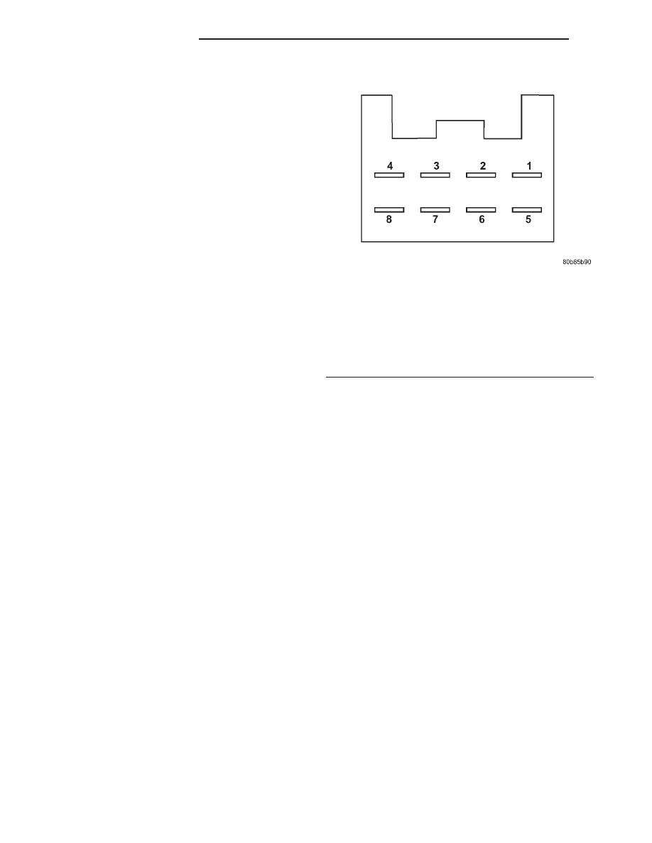
Unplug the wire harness connector at the inopera-

tive power mirror (Fig. 3).

Use two jumper wires, one connected to a 12 - volt

battery feed, and the other connected to a good body
ground. See the Power Mirror Test chart for the cor-
rect jumper wire connections to the power mirror
half of the power mirror wire harness connector. If
the power mirror(s) do not respond as indicated in
the chart, replace the faulty power mirror assembly.
If the power mirror(s) do respond as indicated in the
chart, repair the circuits between the power mirror
and the power mirror switch for a short or open as
required.

REMOVAL

For removal procedures, (Refer to 23 - BODY/EX-

TERIOR/SIDE VIEW MIRROR - REMOVAL).

Fig. 3 Power Mirror Test

Left or Right Mirror

12 Volts

Ground

MIRROR

MOVEMENT

Pin 1

Pin 3

UP

Pin 3

Pin 1

DOWN

Pin 2

Pin 3

LEFT

Pin 3

Pin 2

RIGHT

8N - 16

POWER MIRRORS

AN

POWER SEAT SYSTEM

TABLE OF CONTENTS

page

page

POWER SEAT SYSTEM

DESCRIPTION . . . . . . . . . . . . . . . . . . . . . . . . . . . 17
OPERATION. . . . . . . . . . . . . . . . . . . . . . . . . . . . . 17
DIAGNOSIS AND TESTING . . . . . . . . . . . . . . . . . 17

POWER SEAT SYSTEM . . . . . . . . . . . . . . . . . . 17

DRIVER SEAT SWITCH

DESCRIPTION . . . . . . . . . . . . . . . . . . . . . . . . . . . 17
OPERATION. . . . . . . . . . . . . . . . . . . . . . . . . . . . . 17
DIAGNOSIS AND TESTING . . . . . . . . . . . . . . . . . 18

DRIVER SEAT SWITCH . . . . . . . . . . . . . . . . . . 18

REMOVAL . . . . . . . . . . . . . . . . . . . . . . . . . . . . . . 18
INSTALLATION. . . . . . . . . . . . . . . . . . . . . . . . . . . 18

POWER SEAT TRACK

DESCRIPTION . . . . . . . . . . . . . . . . . . . . . . . . . . . 19
OPERATION. . . . . . . . . . . . . . . . . . . . . . . . . . . . . 19
DIAGNOSIS AND TESTING . . . . . . . . . . . . . . . . . 19

POWER SEAT TRACK . . . . . . . . . . . . . . . . . . . 19

REMOVAL . . . . . . . . . . . . . . . . . . . . . . . . . . . . . . 19
INSTALLATION. . . . . . . . . . . . . . . . . . . . . . . . . . . 19

POWER SEAT SYSTEM

DESCRIPTION

The power seat system option allows the driver to

electrically adjust his seating position for optimum
control and comfort using the power seat switches
located on the outboard seat cushion side shield. The
power seat system allows the seating position to be
adjusted forward, rearward, front up, front down,
rear up, or rear down. The power seat system
receives battery current through a fuse in the Power
Distribution Center, regardless of the ignition switch
position.

The power seat system includes the power seat

adjuster and motors unit (seat track) and the power
seat switch. Following are general descriptions of the
major components in the power seat system. Refer to
the owner’s manual in the vehicle glove box for more
information on the features, use and operation of the
power seat system.

OPERATION

The power seat system receives battery current

through a fuse in the Power Distribution Center
(PDC), regardless of the ignition switch position.

DIAGNOSIS AND TESTING - POWER SEAT
SYSTEM

Before any testing of the power seat system is

attempted, the battery should be fully-charged and
all wire harness connections and pins cleaned and
tightened to ensure proper continuity and grounds.
For circuit descriptions and diagrams, refer to Wiring
Diagrams.

With the dome lamp on, apply the power seat

switch in the direction of the failure. If the dome
lamp dims, the seat may be jamming. Check under

and behind the seat for binding or obstructions. If
the dome lamp does not dim, proceed with testing of
the individual components and circuits.

DRIVER SEAT SWITCH

DESCRIPTION

The power seat can be adjusted in six different

ways using the power seat switch. The switch is
located on the outboard side of the seat cushion side
shield.

The individual switches in the power seat switch

unit cannot be repaired. If one switch is damaged or
faulty, the entire power seat switch unit must be
replaced.

OPERATION

When a power switch control knob or knobs are

actuated, a battery feed and a ground path are
applied through the switch contacts to the power seat
track

or

recliner

adjuster

motor.

The

selected

adjuster motor operates to move the seat track or
recliner through its drive unit in the selected direc-
tion until the switch is released, or until the travel
limit of the adjuster is reached. When the switch is
moved in the opposite direction, the battery feed and
ground path to the motor are reversed through the
switch contacts. This causes the adjuster motor to
run in the opposite direction.

No power seat switch should be held applied in any

direction after the adjuster has reached its travel
limit. The power seat adjuster motors each contain a
self-resetting circuit breaker to protect them from
overload. However, consecutive or frequent resetting
of the circuit breaker must not be allowed to con-
tinue, or the motor may be damaged.

AN

POWER SEAT SYSTEM

8N - 17

DIAGNOSIS AND TESTING - DRIVER SEAT
SWITCH

For circuit descriptions and diagrams, refer to Wir-

ing Diagrams.

(1) Disconnect and isolate the battery negative

cable.

(2) Remove the power seat switch from the power

seat.

(3) With assistance from another person, use an

ohmmeter to test the continuity of the power seat
switches in each position. See the Power Seat Switch
schematic and Continuity chart (Fig. 1) . If OK, see
the Power Seat Track Diagnosis and Testing proce-
dure in this section . If not OK, replace the faulty
power seat switch unit.

REMOVAL

(1) Disconnect and isolate the battery negative

cable.

(2) Remove the screw that secures the recliner

lever to the recliner mechanism release shaft on the
outboard side of the driver side front seat.

(3) Pull the recliner lever off of the recliner mech-

anism release shaft.

(4) Remove the two screws that secure the driver

side seat cushion side shield to the outboard seat
cushion frame.

(5) Pull the driver side seat cushion side shield

away from the seat cushion frame far enough to
access the power seat switch module wire harness
connector.

(6) Unplug the wire harness connector from the

power seat switch module.

(7) Remove the seat cushion side shield and power

seat switch module from the seat as a unit.

(8) Remove the two screws that secure the power

seat switch to the inside of the seat cushion side
shield (Fig. 2).

(9) Remove the power seat switch from the seat

cushion side shield.

INSTALLATION

(1) Install the two screws that secure the power

seat switch to the inside of the seat cushion side
shield.

(2) Install the wire harness connector on the power

seat switch module.

(3) Install the seat cushion side shield and power

seat switch module on the seat as a unit. Refer to
Body for the procedure.

Fig. 1 Power Seat Switch Continuity Test

POWER SEAT SWITCH TEST TABLE

SWITCH POSITION

CONTINUITY BETWEEN

OFF

B & N, B & J, B & M, B &
E, B & L, B & K

VERTICAL UP

A & J, A & N, B & M, B
&E

VERTICAL DOWN

A & E, A & M, B & N, B &
J

HORIZONTAL
FORWARD

A & K, B & L

HORIZONTAL AFT

A & L, B & K

FRONT TILT UP

A & J, B & E

FRONT TILT DOWN

A & E, B & J

REAR TILT UP

A & N, B & M

REAR TILT DOWN

A & M, B & N

Fig. 2 Power Seat Switch Remove/Install - Typical

1 - Seat Side Shield
2 - Power Seat Switch
3 - Screws

8N - 18

POWER SEAT SYSTEM

AN

DRIVER SEAT SWITCH (Continued)

(4) Install the recliner lever on the recliner mech-

anism release shaft.

(5) Install the screw that secures the recliner lever

to the recliner mechanism release shaft on the out-
board side of the driver side front seat.

(6) Connect the battery negative cable.

POWER SEAT TRACK

DESCRIPTION

Vehicles equipped with the power seat option, uti-

lize a power seat track. Three reversible DC motors
are incorporated into the power seat track. The
motors are connected to worm-drive gearboxes that
move the seat track through a combination of screw-
type drive units.

The front and rear of the seat are operated by dif-

ferent motors. They can be raised or lowered inde-
pendently of each other. When the center power seat
switch is pushed in the Up or Down direction, both
the front and rear motors operate in unison. On stan-
dard cab models the entire seat is moved up or down.
On extended cab models the seat cushion moves
independently of the seat back in the up or down
directions.

Each motor contains a self-resetting circuit breaker

to protect it from overload. Consecutive or frequent
resetting of the circuit breakers must not be allowed
to continue, or the motors may be damaged.

The power seat track (adjuster) cannot be repaired,

and is serviced only as a complete assembly. If any
component in this assembly is faulty or damaged, the
entire power seat track must be replaced.

OPERATION

When a power seat switch is actuated, a battery

feed and a ground path are applied through the
power seat switch contacts to the appropriate motor
or motors. The motor and drive unit operate to move
the seat in the selected direction until the switch is
released, or until the travel limit of the power seat
track is reached. When the switch is moved in the
opposite direction, the battery feed and ground path
to the motor is reversed through the switch contacts.
This causes the motor to run in the opposite direc-
tion.

DIAGNOSIS AND TESTING - POWER SEAT
TRACK

For complete power seat circuit descriptions and

diagrams, refer to Wiring Diagrams.

Operate the power seat switch to move all three

seat motors in each direction. The seat should move
in each of the selected directions. If the power seat
track fails to operate in only one direction, move the

seat track a short distance in the opposite direction
and test again to be certain that the track is not at
its travel limit. If the power seat track still fails to
operate in only one direction, refer to Diagnosis and
Testing of the Power Seat Switch in this section. If
the power seat track fails to operate in more than
one direction, proceed as follows:

(1) Check the power seat fuse in the power distri-

bution center. If OK, go to Step 2. If not OK, replace
the faulty fuse.

(2) Remove the power seat switch from the seat.

Check for battery voltage at the fused B(+) circuit
cavity of the power seat switch wire harness connec-
tor. If OK, go to Step 3. If not OK, repair the open
circuit to the power distribution center as required.

(3) Check for continuity between the ground cir-

cuit cavity of the power seat switch wire harness con-
nector

and

a

good

ground.

There

should

be

continuity. If OK, go to Step 4. If not OK, repair the
open circuit to ground as required.

(4) Test the power seat switch as described in this

group. If the switch tests OK, check the wire harness
between the power seat switch and the motor for
shorts or opens. If the circuits check OK, replace the
faulty power seat track (adjuster) assembly. If the
circuits are not OK, repair the wire harness as
required.

REMOVAL

(1) Disconnect and isolate the battery negative

cable.

(2) Remove the driver side seat assembly from the

vehicle. Refer to the Body section of the service man-
ual for the procedure.

(3) Disconnect the power seat wire harness connec-

tors.

(4) Disconnect the power seat wire harness retain-

ers from the seat track assembly.

(5) Remove the four bolts that secure the power

seat track assembly to the seat cushion frame.

(6) If the vehicle is equipped with a split bench

seat, remove the fasteners that secure the center seat
cushion section to the brackets on the power seat
track assembly.

(7) Remove the power seat track assembly from

the seat cushion frame.

CAUTION: Before installing the seat into the vehi-
cle, be certain to adjust the seat fully rearward on
its tracks. Then install and tighten the front track
mounting screws before installing the rear screws
or the tracks may be damaged.

INSTALLATION

(1) Position the power seat track assembly on the

seat cushion frame and compare the old and replace-

AN

POWER SEAT SYSTEM

8N - 19

DRIVER SEAT SWITCH (Continued)


Content   ..  341  342  343  344   ..