Dodge Dakota (R1). Manual - part 341


  Index      Dodge     Dodge Dakota (R1) - service repair manual 2000 year


Search            


Content   ..  339  340  341  342   ..


Dodge Dakota (R1). Manual - part 341


Disconnect the door wire harness connectors for the
DDM from the DDM connector receptacles.

(2) Test the DDM switch continuity. See the Driver

Door Module Switch Tests chart to determine if the
continuity is correct for the suspect switches in each
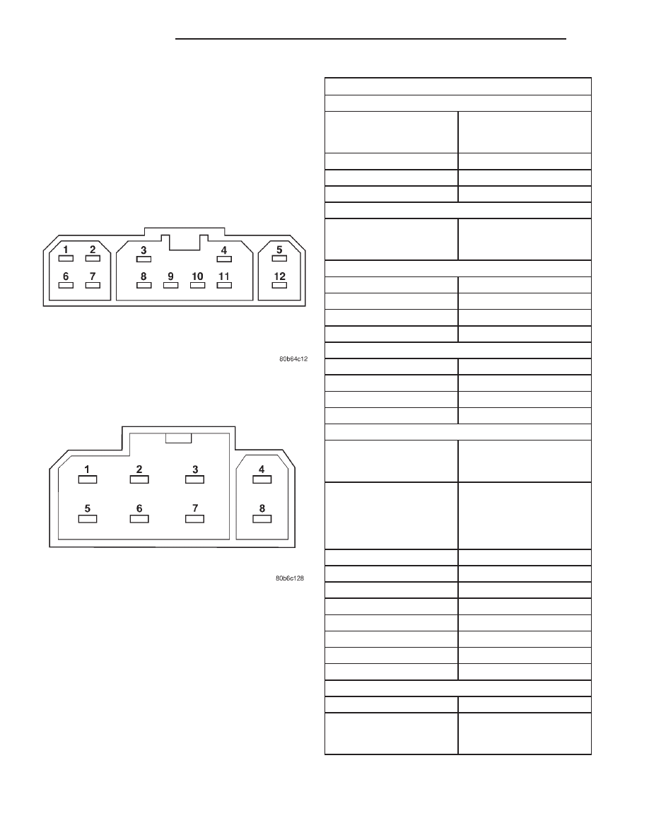
switch position (Fig. 2) and/or (Fig. 3). If not OK,
replace the faulty DDM as required.

DRIVER DOOR MODULE SWITCH TESTS

POWER LOCK SWITCH

SWITCH POSITION

RESISTANCE BETWEEN

CONNECTOR C-1 PINS

7 & 11

NEUTRAL

10 KILOHMS ± 1%

LOCK

820 OHMS ± 1%

UNLOCK

320 OHMS ± 1%

POWER MIRROR SWITCH

SWITCH POSITION

CONTINUITY BETWEEN

PINS OF CONNECTOR

C-2

LEFT MIRROR SELECTED

UP

PINS 1 & 3

DOWN

PINS 2 & 3

RIGHT

PINS 2 & 3

LEFT

PINS 3 & 6

RIGHT MIRROR SELECTED

UP

PINS 3 & 7

DOWN

PINS 2 & 3

RIGHT

PINS 2 & 3

LEFT

PINS 3 & 4

POWER WINDOW SWITCH

SWITCH POSITION

CONTINUITY BETWEEN

PINS OF CONNECTOR

C-1

NEUTRAL

PINS 1 & 8, PINS 2 & 8,
PINS 3 & 8, PINS 4 & 8,
PINS 5 & 8, PINS 6 & 8,

PINS 8 & 10, PINS 8 &

12

LEFT FRONT UP

PINS 5 & 9

LEFT FRONT DOWN

PINS 9 & 12

RIGHT FRONT UP

PINS 3 & 9

RIGHT FRONT DOWN

PINS 6 & 9

LEFT REAR UP

PINS 4 & 9

LEFT REAR DOWN

PINS 9 & 10

RIGHT REAR UP

PINS 2 & 9

RIGHT REAR DOWN

PINS 1 & 9

POWER WINDOW LOCKOUT SWITCH

SWITCH POSITION

CONTINUITY BETWEEN

OFF (SWITCH BUTTON

RAISED - NOT

DEPRESSED)

PIN 9 OF CONNECTOR

C-1 & PIN 8 OF

CONNECTOR C-2

Fig. 2 Driver Door Module Connector C1 Receptacle

Fig. 3 Driver Door Module Connector C2 Receptacle

8N - 8

POWER LOCKS

AN

DRIVER DOOR MODULE (Continued)

REMOVAL

(1) Disconnect and isolate the battery negative

cable.

(2) Using a trim stick or another suitable wide flat

bladed tool and starting at the rear of the Driver
Door Module (DDM) bezel, gently pry the DDM up
and out from the driver side front door trim panel
(Fig. 4).

(3) Pull the DDM away from the trim panel open-

ing far enough to access the two connector recepta-
cles on the back of the unit.

(4) Disconnect the two door wire harness connec-

tors for the DDM from the DDM connector recepta-
cles.

(5) Remove the DDM from the door trim panel.

INSTALLATION

(1) Position the Driver Door Module (DDM) to the

opening in the driver side front door trim panel.

(2) Reconnect the two door wire harness connec-

tors for the DDM to the DDM connector receptacles.

(3) Insert the front of the DDM bezel into the

opening in the driver side front door trim panel (Fig.
4).

(4) Using hand pressure, gently and evenly press

down on the rear of the DDM bezel until it snaps
into place.

(5) Reconnect the battery negative cable.

POWER LOCK MOTOR

DESCRIPTION

Models equipped with the optional power lock sys-

tem have a power operated locking mechanism
located within each door. The lock mechanisms are
actuated by a reversible electric power lock motor.
This motor is integral to the door latch unit within

each door. A single short pigtail wire with a molded
plastic connector insulator connects each lock motor
to the vehicle electrical system through a take out
and connector of the wire harness within each door.

The power lock motors cannot be adjusted or

repaired and, if faulty or damaged, the entire door
latch unit must be replaced.

OPERATION

The driver side front door power lock motor is con-

trolled by a unique driver unlock relay output of the
Central Timer Module (CTM), while the remaining
power lock motors are all connected in parallel and
share common CTM lock and unlock relay outputs.
The driver side front door power lock motor also
shares the common lock relay output from the CTM.
This circuit arrangement makes the Remote Keyless
Entry (RKE) system driver door unlock only feature
option for quad cab models possible. A positive and
negative battery connection to the two power lock
motor terminals will cause the power lock motor
plunger to move in one direction. Reversing the cur-
rent through these same two connections will cause
the power lock motor plunger to move in the opposite
direction. The power lock motors and circuits can be
tested using conventional diagnostic tools and meth-
ods.

DIAGNOSIS AND TESTING - POWER LOCK
MOTOR

Before you proceed with this diagnosis, confirm

proper power lock switch, Central Timer Module
(CTM), and power lock switch output circuit opera-
tion. Remember, the CTM circuitry controls the out-
put to each of the power lock motors. Refer to the
appropriate wiring information. The wiring informa-
tion includes wiring diagrams, proper wire and con-
nector repair procedures, details of wire harness
routing and retention, connector pin-out information
and location views for the various wire harness con-
nectors, splices and grounds.

(1) Check each power lock motor for correct opera-

tion while moving the power lock switch to both the
Lock and Unlock positions. If all of the power lock
motors are inoperative, go to Step 2. If one power
lock motor is inoperative, go to Step 3.

(2) If all of the power lock motors are inoperative,

the problem may be caused by one shorted motor.
Disconnecting a shorted power lock motor from the
power lock circuit will allow the good power lock
motor to operate. Disconnect the wire harness con-
nector from each power lock motor, one at a time,
and recheck both the lock and unlock functions by
operating the power lock switch. If all of the power
lock motors are still inoperative after the above test,
check for a short or open circuit between the power

Fig. 4 Driver Door Module

AN

POWER LOCKS

8N - 9

DRIVER DOOR MODULE (Continued)

lock motors and the CTM. If disconnecting one power
lock motor causes the other motors to become func-
tional, go to Step 3 to test the disconnected motor.

(3) Once it has been determined which power lock

motor is inoperative, that motor can be tested as fol-
lows. Disconnect the wire harness connector from the
inoperative power lock motor. Apply 12 volts to the
lock and unlock driver circuit cavities of the power
lock motor pigtail wire connector to check its opera-
tion in one direction. Reverse the polarity to check
the motor operation in the opposite direction. If OK,
repair the shorted or open lock or unlock driver cir-
cuits between the power lock motor and the CTM as
required. If not OK, replace the faulty power lock
motor.

POWER LOCK SWITCH

DESCRIPTION

The power lock system can be controlled by a two-

way, momentary, resistor multiplexed, single gang
switch on a power lock and window switch bezel
located near the forward end of the armrest on the
passenger side front door trim panel. The power lock
switch on the driver side front door trim panel is
integral to the driver door module. (Refer to 8 -
ELECTRICAL/POWER

LOCKS/DRIVER

DOOR

MODULE - DESCRIPTION). The power lock switch
is secured by integral latch tabs in a molded plastic
receptacle on the back side of the power window and
lock switch bezel so that only the switch paddle is
visible where it protrudes through the bezel. The
power window and lock switch bezel is secured by
small metal snap clips within an opening near the
forward end of the arm rest in the passenger side
front door trim panel so that the switches can be ser-
viced without removing the front door trim panel. An
integral connector receptacle on the back of the
switch connects it to the vehicle electrical system
through a take out and connector of the right front
door wire harness. The power lock switch has a green
Light-Emitting Diode (LED) located in the switch
paddle to improve switch visibility in dark ambient
lighting conditions. The power lock switch cannot be
adjusted or repaired and, if faulty or damaged, the
switch unit must be replaced.

OPERATION

The two-way, momentary, power lock switch on the

passenger side front door is connected in series
between ground and the passenger door switch mux
input of the Central Timer Module (CTM). The power
lock switch on the driver side front door trim panel is
integral to the driver door module. (Refer to 8 -
ELECTRICAL/POWER

LOCKS/DRIVER

DOOR

MODULE - OPERATION). Each power lock switch
position Lock, Unlock, and Neutral provides a differ-
ent resistance value to the CTM input which allows
the CTM to sense the switch position. Based upon
the power lock switch inputs, the CTM controls the
battery and ground feed outputs to the power lock
motors to lock or unlock the door and liftgate latches.
The Light-Emitting Diode (LED) in the paddle of the
passenger door power lock switch is connected to bat-
tery current through a fuse in the Junction Block
(JB) on a fused ignition switch output (run) circuit;
therefore, the switch will only be illuminated when
the ignition switch is in the On position. The power
lock switch can be diagnosed using conventional
diagnostic tools and methods.

DIAGNOSIS AND TESTING - POWER LOCK
SWITCH

The Light-Emitting Diode (LED) illumination lamp

of the power lock switch receives battery current
through a fuse in the Junction Block (JB) on a fused
ignition switch output (run) circuit. The power lock
switch on the driver side front door trim panel is
integral to the driver door module. (Refer to 8 -
ELECTRICAL/POWER

LOCKS/DRIVER

DOOR

MODULE - DIAGNOSIS AND TESTING). If the
power lock switch operates, but the LED is inopera-
tive, check for battery current at the switch with the
ignition switch in the On position. If OK, replace the
faulty switch. Refer to the appropriate wiring infor-
mation. The wiring information includes wiring dia-
grams, proper wire and connector repair procedures,
details of wire harness routing and retention, connec-
tor pin-out information and location views for the
various wire harness connectors, splices and grounds.

(1) Disconnect and isolate the battery negative

cable. Remove the power lock switch from the door
trim panel. Disconnect the door wire harness connec-
tor for the power lock switch from the switch connec-
tor receptacle.

(2) Test the power lock switch resistance. See the

Power Lock Switch Test chart to determine if the
resistance is correct for the switch in each switch
position (Fig. 5). If not OK, replace the faulty power
lock switch as required.

8N - 10

POWER LOCKS

AN

POWER LOCK MOTOR (Continued)

POWER LOCK SWITCH TEST

SWITCH POSITION

RESISTANCE BETWEEN

PINS 1 & 5

NEUTRAL

10 KILOHMS ±1%

LOCK

820 OHMS ±1%

UNLOCK

330 OHMS ±1%

REMOVAL

The power lock switch on the driver side front door

trim panel is integral to the driver door module.
(Refer to 8 - ELECTRICAL/POWER LOCKS/DRIVER
DOOR MODULE - REMOVAL).

(1) Disconnect and isolate the battery negative

cable.

(2) Using a trim stick or another suitable wide flat

bladed tool and starting at the rear of the passenger
door power window and lock switch bezel, gently pry
the bezel up and out from the passenger side front
door trim panel.

(3) Pull the power window and lock switch bezel

away from the trim panel opening far enough to
access the two switch connector receptacles on the
back of the unit.

(4) Disconnect the door wire harness connectors

for the power lock and power window switches from
the switch connector receptacles.

(5) Remove the power window and lock switch

bezel from the door trim panel.

(6) Using a small thin-bladed screwdriver, gently

pry the snap clips at the sides of the power lock
switch receptacle on the back of the power window
and lock switch bezel and pull the switch out of the
receptacle.

INSTALLATION

The power lock switch on the driver side front door

trim panel is integral to the driver door module.
(Refer to 8 - ELECTRICAL/POWER LOCKS/DRIVER
DOOR MODULE - INSTALLATION).

(1) Align the power lock switch with the receptacle

on the back of the power window and lock switch
bezel.

(2) Using hand pressure, gently and evenly press

down on the power lock switch it snaps into place in
the power window and lock switch bezel receptacle.

(3) Position the power window and lock switch

bezel to the opening in the passenger side front door
trim panel.

(4) Reconnect the two door wire harness connec-

tors for the power window and power lock switches to
the switch connector receptacles.

(5) Insert the front of the power window and lock

switch bezel into the opening in the passenger side
front door trim panel.

(6) Using hand pressure, gently and evenly press

down on the rear of the power window and lock
switch bezel until it snaps into place.

(7) Reconnect the battery negative cable.

REMOTE KEYLESS ENTRY
TRANSMITTER

DESCRIPTION

The Remote Keyless Entry (RKE) system Radio

Frequency (RF) transmitter is equipped with three
buttons, labeled Lock, Unlock, and Panic. It is also
equipped with a key ring and is designed to serve as
a key fob. The operating range of the transmitter
radio signal is up to 7 meters (23 feet) from the RKE
receiver. The RKE receiver is integral to the Central
Timer Module (CTM) in this vehicle.

Each RKE transmitter has a different vehicle

access code, which must be programmed into the
memory of the RKE receiver in the vehicle in order
to operate the RKE system. The RKE receiver can
retain the access codes for up to four transmitters in
its memory. (Refer to 8 - ELECTRICAL/POWER
LOCKS/REMOTE KEYLESS ENTRY TRANSMIT-
TER - STANDARD PROCEDURE - RKE TRANS-
MITTER PROGRAMMING).

The RKE transmitter operates on two Duracell

DL2016, Panasonic CR2016 (or equivalent) batteries.
Typical battery life is from one to two years. The

Fig. 5 Power Lock Switch Connector Receptacle

AN

POWER LOCKS

8N - 11

POWER LOCK SWITCH (Continued)


Content   ..  339  340  341  342   ..