Dodge Dakota (R1). Manual - part 331


  Index      Dodge     Dodge Dakota (R1) - service repair manual 2000 year


Search            


Content   ..  329  330  331  332   ..


Dodge Dakota (R1). Manual - part 331


REMOVAL

WARNING: ON VEHICLES EQUIPPED WITH AIR-
BAGS, DISABLE THE AIRBAG SYSTEM BEFORE
ATTEMPTING ANY STEERING WHEEL, STEERING
COLUMN, SEAT BELT TENSIONER, OR INSTRU-
MENT PANEL COMPONENT DIAGNOSIS OR SER-
VICE. DISCONNECT AND ISOLATE THE BATTERY
NEGATIVE (GROUND) CABLE, THEN WAIT TWO
MINUTES FOR THE AIRBAG SYSTEM CAPACITOR
TO DISCHARGE BEFORE PERFORMING FURTHER
DIAGNOSIS OR SERVICE. THIS IS THE ONLY SURE
WAY TO DISABLE THE AIRBAG SYSTEM. FAILURE
TO TAKE THE PROPER PRECAUTIONS COULD
RESULT IN ACCIDENTAL AIRBAG DEPLOYMENT
AND POSSIBLE PERSONAL INJURY.

(1) Disconnect and isolate the battery negative

cable.

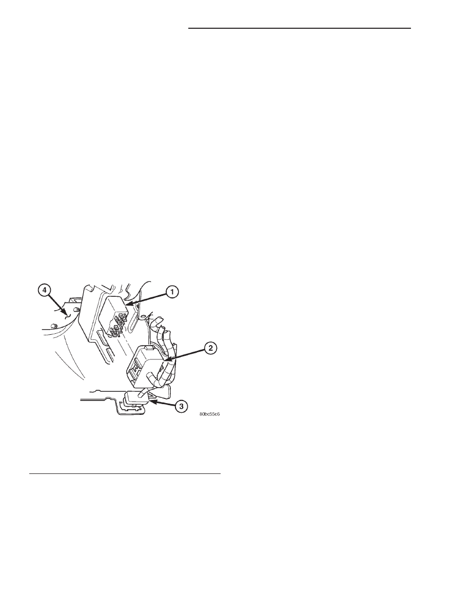
(2) Reach under the outboard side of the steering

column opening in the instrument panel to access the
instrument panel wire harness connector for the com-
bination flasher located on a mounting tab on the
back of the instrument panel armature (Fig. 4).

(3) Grasp the combination flasher and connector

firmly and pull them toward the dash panel to disen-
gage the connector from the mounting tab on the
instrument panel armature.

(4) Remove the combination flasher from the

instrument panel wire harness connector.

INSTALLATION

WARNING: ON VEHICLES EQUIPPED WITH AIR-
BAGS, DISABLE THE AIRBAG SYSTEM BEFORE
ATTEMPTING ANY STEERING WHEEL, STEERING
COLUMN, SEAT BELT TENSIONER, OR INSTRU-
MENT PANEL COMPONENT DIAGNOSIS OR SER-
VICE. DISCONNECT AND ISOLATE THE BATTERY
NEGATIVE (GROUND) CABLE, THEN WAIT TWO
MINUTES FOR THE AIRBAG SYSTEM CAPACITOR
TO DISCHARGE BEFORE PERFORMING FURTHER
DIAGNOSIS OR SERVICE. THIS IS THE ONLY SURE
WAY TO DISABLE THE AIRBAG SYSTEM. FAILURE
TO TAKE THE PROPER PRECAUTIONS COULD
RESULT IN ACCIDENTAL AIRBAG DEPLOYMENT
AND POSSIBLE PERSONAL INJURY.

(1) Position the combination flasher to the instru-

ment panel wire harness connector (Fig. 4).

(2) Align the combination flasher terminals with

the terminal cavities in the instrument panel wire
harness connector.

(3) Using hand pressure, push in firmly on the

combination flasher until the terminals are fully
seated in the terminal cavities in the instrument
panel wire harness connector.

(4) Align the slot in the combination flasher con-

nector with the mounting tab on the instrument
panel armature.

(5) Using hand pressure, push the combination

flasher connector firmly onto the mounting tab until
it is fully engaged in the slot.

(6) Reconnect the battery negative cable.

Fig. 4 Combination Flasher

1 - COMBINATION FLASHER
2 - INSTRUMENT PANEL WIRE HARNESS CONNECTOR
3 - 16-WAY DATA LINK CONNECTOR
4 - STEERING COLUMN OPENING COVER

8L - 12

LAMPS/LIGHTING - EXTERIOR

AN

COMBINATION FLASHER (Continued)

FOG LAMP

REMOVAL

(1) Disconnect and isolate the battery negative

cable.

(2) Disengage fog lamp harness connector.
(3) Rotate bulb socket a 1/4 turn counterclockwise

and pull from lamp to separate (Fig. 5).

(4) Grasp bulb and pull from lamp.

INSTALLATION

CAUTION: Do not touch the bulb glass with fingers
or other oily surfaces. Reduced bulb life will result.

(1) Position bulb in lamp, push to seat and rotate

a 1/4 turn clockwise.

(2) Connect fog lamp harness connector.
(3) Connect the battery negative cable.

FOG LAMP UNIT

REMOVAL

NOTE: The fog lamps are serviced from the rear-
ward side of the front bumper.

(1) Disconnect and isolate the battery negative

cable.

(2) Disengage fog lamp harness connector.
(3) Remove the bolts attaching the fog lamp to the

bumper (Fig. 6).

(4) Separate fog lamp from bumper.

INSTALLATION

(1) Position fog lamp in bumper.
(2) Install the bolts attaching the fog lamp to the

bumper.

(3) Connect fog lamp harness connector.
(4) Check for proper operation and beam align-

ment.

(5) Connect the battery negative cable.

ADJUSTMENTS - FOG LAMP UNIT

Prepare an alignment screen. (Refer to 8 - ELEC-

TRICAL/LAMPS/LIGHTING

-

EXTERIOR/HEAD-

LAMP UNIT - ADJUSTMENTS). A properly aligned
fog lamp will project a pattern on the alignment
screen 100 mm (4 in.) below the fog lamp centerline
and straight ahead (Fig. 7). Rotate the adjustment
screw to adjust beam height (Fig. 8).

Fig. 5 Fog Lamp Bulb

1 - FOG LAMP
2 - FOG LAMP BULB

Fig. 6 Fog Lamp

1 - FOG LAMP
2 - FRONT BUMPER

AN

LAMPS/LIGHTING - EXTERIOR

8L - 13

HEADLAMP SWITCH

DESCRIPTION

The headlamp switch is located on the instrument

panel. The headlamp switch controls the parking
lamps, the headlamps, the interior lamps and the
instrument

cluster

illumination.

The

headlamp

switch also contains a rheostat for controlling the
illumination level of the instrument cluster lamps.

OPERATION

The headlamp switch closes a path to ground for

the Central Timer Module (CTM) when the park or
head lamps are on and the driver door ajar switch is
closed (driver door is open). The headlamp switch
opens the ground path when the headlamp switch is
turned off. The ground path is also opened when the
driver door ajar switch is open (driver door is closed).

Fig. 7 Fog Lamp Alignment

1 - VEHICLE CENTERLINE
2 - CENTER OF VEHICLE TO CENTER OF FOG LAMP LENS
3 - HIGH-INTENSITY AREA
4 - FLOOR TO CENTER OF FOG LAMP LENS

5 - 100 mm (4 in.)
6 - 7.62 METERS (25 FEET)
7 - FRONT OF FOG LAMP

Fig. 8 Fog Lamp Adjustment

1 - FOG LAMP
2 - ADJUSTMENT SCREW

8L - 14

LAMPS/LIGHTING - EXTERIOR

AN

FOG LAMP UNIT (Continued)

The headlamp switch cannot be repaired and, if

faulty or damaged, it must be replaced. (Refer to 8 -
ELECTRICAL/LAMPS/LIGHTING

-

EXTERIOR/

HEADLAMP SWITCH - REMOVAL) for the service
procedures.

DIAGNOSIS AND TESTING - HEADLAMP
SWITCH

WARNING: ON VEHICLES EQUIPPED WITH AIR-
BAGS,

REFER

TO

ELECTRICAL,

RESTRAINTS

BEFORE ATTEMPTING ANY STEERING WHEEL,
STEERING

COLUMN,

OR

INSTRUMENT

PANEL

COMPONENT DIAGNOSIS OR SERVICE. FAILURE
TO TAKE THE PROPER PRECAUTIONS COULD
RESULT IN ACCIDENTAL AIRBAG DEPLOYMENT
AND POSSIBLE PERSONAL INJURY.

(1) Remove the headlamp switch. (Refer to 8 -

ELECTRICAL/LAMPS/LIGHTING

-

EXTERIOR/

HEADLAMP SWITCH - REMOVAL).

(2) Using an ohmmeter, test for continuity between

the terminals of the switch as shown in the Head-
lamp Switch Continuity table (Fig. 9).

(3) If test results are not obtained as shown in the

Headlamp Switch Continuity table, replace the head-
lamp switch.

For circuit descriptions and diagrams, refer to the

appropriate wiring information. The wiring informa-
tion includes wiring diagrams, proper wire and con-
nector repair procedures, details of wire harness
routing and retention, connector pin-out information
and location views for the various wire harness con-
nectors, splices and grounds.

HEADLAMP SWITCH CONTINUITY TABLE

SWITCH POSITION

CONTINUITY BETWEEN

OFF

PIN 2 AND 4, PIN 1 AND

14

PARK

PIN 3 AND 4

HEAD

PIN 4 AND 6

FOG LAMP

PIN 5 AND 4

INTERIOR LAMPS

DIMMER

PIN 12 AND 9, PIN 1

AND 14, PIN 1 AND 8

PARADE

PIN 1 AND 14, PIN 12

AND 9

DOME

PIN 1 AND 8, PIN 1 AND

14, PIN 10 AND 9

CARGO

PIN 1 AND 14, PIN 1

AND 8, PIN 10 AND 9,

PIN 11 AND 9

REMOVAL

WARNING: ON VEHICLES EQUIPPED WITH AIR-
BAGS,

REFER

TO

ELECTRICAL,

RESTRAINTS

BEFORE ATTEMPTING ANY STEERING WHEEL,
STEERING

COLUMN,

OR

INSTRUMENT

PANEL

COMPONENT DIAGNOSIS OR SERVICE. FAILURE
TO TAKE THE PROPER PRECAUTIONS COULD
RESULT IN ACCIDENTAL AIRBAG DEPLOYMENT
AND POSSIBLE PERSONAL INJURY.

(1) Disconnect and isolate the battery negative

cable.

(2) Remove the cluster bezel from the instrument

panel (Refer to 23 - BODY/INSTRUMENT PANEL/
CLUSTER BEZEL - REMOVAL).

(3) Disconnect the wire harness connector from the

headlamp switch.

(4) Remove the headlamp switch from the cluster

bezel.

INSTALLATION

WARNING: ON VEHICLES EQUIPPED WITH AIR-
BAGS,

REFER

TO

ELECTRICAL,

RESTRAINTS

BEFORE ATTEMPTING ANY STEERING WHEEL,
STEERING

COLUMN,

OR

INSTRUMENT

PANEL

COMPONENT DIAGNOSIS OR SERVICE. FAILURE
TO TAKE THE PROPER PRECAUTIONS COULD
RESULT IN ACCIDENTAL AIRBAG DEPLOYMENT
AND POSSIBLE PERSONAL INJURY.

(1) Position the headlamp switch to the cluster

bezel.

Fig. 9 HEADLAMP SWITCH

AN

LAMPS/LIGHTING - EXTERIOR

8L - 15

HEADLAMP SWITCH (Continued)


Content   ..  329  330  331  332   ..