Dodge Dakota (R1). Manual - part 299


  Index      Dodge     Dodge Dakota (R1) - service repair manual 2000 year


Search            


Content   ..  297  298  299  300   ..


Dodge Dakota (R1). Manual - part 299


the terminal clamp pinch-bolt hex nut to 7.9 N·m (70
in. lbs.).

(6) Reconnect the battery negative cable terminal

clamp to the battery negative terminal post. Tighten
the terminal clamp pinch-bolt hex nut to 7.9 N·m (70
in. lbs.).

(7) Apply a thin coating of petroleum jelly or chas-

sis grease to the exposed surfaces of the battery cable
terminal clamps and the battery terminal posts.

BATTERY HOLDDOWN

DESCRIPTION

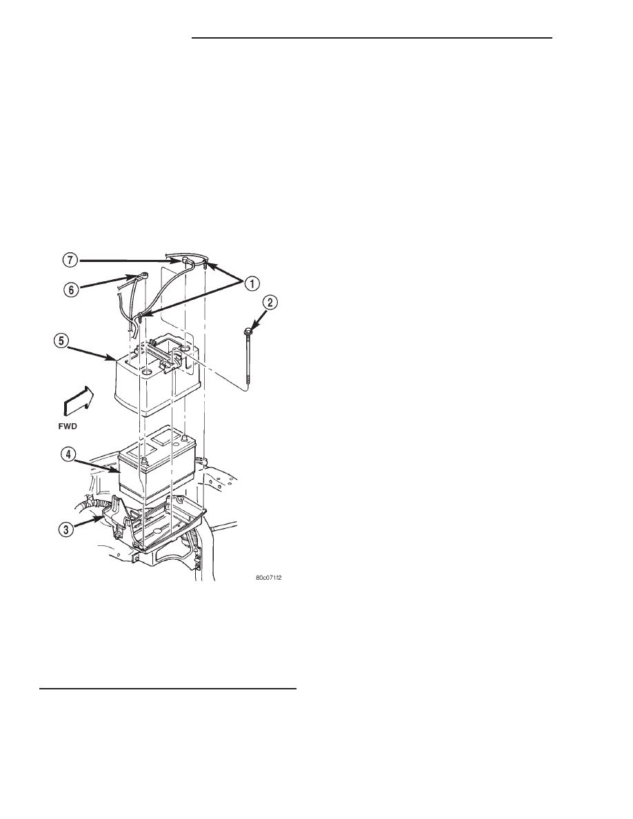
The battery hold down hardware (Fig. 18) includes

two bolts, two U-nuts and a hold down strap/battery
thermoguard unit. The molded plastic battery hold
down strap is integral to the battery thermoguard
unit, which encloses the sides of the battery case.

When installing a battery into the battery tray, be

certain that the hold down hardware is properly
installed and that the fasteners are tightened to the
proper specifications. Improper hold down fastener
tightness, whether too loose or too tight, can result in
damage to the battery, the vehicle or both. Refer to
Battery Hold Downs in this section for the location
of the proper battery hold down installation proce-
dures, including the proper hold down fastener tight-
ness specifications.

OPERATION

The battery holddown secures the battery in the

battery tray. This holddown is designed to prevent
battery movement during the most extreme vehicle
operation conditions. Periodic removel and lubrica-
tion of the battery holddown hardware is recomended
to prevent hardware seizure at a later date.

NOTE: Never operate a vehicle without a battery
holddown device properly installed. Damage to the
vehicle, components and battery could result.

REMOVAL

(1) Turn the ignition switch to the Off position. Be

certain that all electrical accessories are turned off.

(2) Loosen the battery negative cable terminal

clamp pinch-bolt hex nut.

(3) Disconnect the battery negative cable terminal

clamp from the battery negative terminal post. If
necessary, use a battery terminal puller to remove
the terminal clamp from the battery post.

(4) Disconnect the battery positive cable terminal

clamp from the battery positive terminal post. If nec-
essary, use a battery terminal puller to remove the
terminal clamp from the battery post.

(5) Remove the two hold down bolts that secure

the hold down strap/battery thermal guard unit to
the U-nuts in the battery tray (Fig. 19).

(6) Remove the hold down strap/battery thermal

guard unit from the top of the battery case.

INSTALLATION

(1) Clean and inspect the battery hold down hard-

ware. Refer to Battery in the index of this service
manual for the location of the proper battery hold
down hardware cleaning and inspection procedures.

(2) Install the hold down strap/battery thermo-

guard unit over the top of the battery case.

(3) Install and tighten the two hold down bolts

that secure the hold down strap/battery thermoguard
unit to the U-nuts in the battery tray. Tighten the
bolts to 2.1 N·m (19 in. lbs.).

(4) Reconnect the battery positive cable terminal

clamp to the battery positive terminal post. Tighten

Fig. 18 Battery Hold Downs

1 - CLIPS
2 - BOLT
3 - TRAY
4 - BATTERY
5 - HOLD DOWN STRAP AND THERMAL GUARD
6 - POSITIVE CABLE
7 - NEGATIVE CABLE

8F - 18

BATTERY SYSTEM

AN

BATTERY (Continued)

the terminal clamp pinch-bolt hex nut to 7.9 N·m (70
in. lbs.).

(5) Reconnect the battery negative cable terminal

clamp to the battery negative terminal post. Tighten
the terminal clamp pinch-bolt hex nut to 7.9 N·m (70
in. lbs.).

BATTERY CABLE

DESCRIPTION

The battery cables (Fig. 20) are large gauge,

stranded copper wires sheathed within a heavy plas-
tic or synthetic rubber insulating jacket. The wire
used in the battery cables combines excellent flexibil-
ity and reliability with high electrical current carry-
ing capacity. Refer to Wiring Diagrams in the index
of this service manual for the location of the proper
battery cable wire gauge information.

The battery cables cannot be repaired and, if dam-

aged or faulty they must be replaced. Both the bat-
tery positive and negative cables are available for
service replacement only as a unit with the battery
positive cable wire harness or the battery negative
cable wire harness, which may include portions of
the wiring circuits for the generator and other com-
ponents on some models. Refer to Wiring Diagrams
in the index of this service manual for the location of
more information on the various wiring circuits
included in the battery cable wire harnesses for the
vehicle being serviced.

The battery cables feature a stamped brass clamp-

ing type female battery terminal crimped onto one
end of the battery cable wire and then solder-dipped.
A square headed pinch-bolt and hex nut are installed
at the open end of the female battery terminal clamp.
The battery positive cable also includes a red molded
rubber protective cover for the female battery termi-
nal clamp. Large eyelet type terminals are crimped
onto the opposite end of the battery cable wire and
then solder-dipped. The battery positive cable wires
have a red insulating jacket to provide visual identi-
fication and feature a larger female battery terminal
clamp to allow connection to the larger battery posi-
tive terminal post. The battery negative cable wires
have a black insulating jacket and a smaller female
battery terminal clamp.

OPERATION

The battery cables connect the battery terminal

posts to the vehicle electrical system. These cables
also provide a return path for electrical current gen-

Fig. 19 Battery Hold Downs Remove/Install

1 - CLIPS
2 - BOLT
3 - TRAY
4 - BATTERY
5 - HOLD DOWN STRAP AND THERMAL GUARD
6 - POSITIVE CABLE
7 - NEGATIVE CABLE

Fig. 20 Battery Cables

1 - POWER DISTRIBUTION CENTER
2 - CLIP
3 - BATTERY
4 - TRAY
5 - NEGATIVE CABLE
6 - POSITIVE CABLE
7 - CLIP
8 - WHEELHOUSE INNER PANEL

AN

BATTERY SYSTEM

8F - 19

BATTERY HOLDDOWN (Continued)

erated by the charging system for restoring the volt-
age potential of the battery. The female battery
terminal clamps on the ends of the battery cable
wires provide a strong and reliable connection of the
battery cable to the battery terminal posts. The ter-
minal pinch bolts allow the female terminal clamps
to be tightened around the male terminal posts on
the top of the battery. The eyelet terminals secured
to the ends of the battery cable wires opposite the
female battery terminal clamps provide secure and
reliable connection of the battery to the vehicle elec-
trical system.

DIAGNOSIS & TESTING - BATTERY CABLES

DIAGNOSIS

A voltage drop test will determine if there is exces-

sive resistance in the battery cable terminal connec-
tions or the battery cables. If excessive resistance is
found in the battery cable connections, the connec-
tion point should be disassembled, cleaned of all cor-
rosion

or

foreign

material,

then

reassembled.

Following reassembly, check the voltage drop for the
battery cable connection and the battery cable again
to confirm repair.

When performing the voltage drop test, it is impor-

tant to remember that the voltage drop is giving an
indication of the resistance between the two points at
which the voltmeter probes are attached. EXAM-
PLE: 
When testing the resistance of the battery pos-
itive cable, touch the voltmeter leads to the battery
positive cable terminal clamp and to the battery pos-
itive cable eyelet terminal at the starter solenoid
B(+) terminal stud. If you probe the battery positive
terminal post and the battery positive cable eyelet
terminal at the starter solenoid B(+) terminal stud,
you are reading the combined voltage drop in the
battery positive cable terminal clamp-to-terminal
post connection and the battery positive cable.

TESTING

VOLTAGE DROP TEST

WARNING:

• IF THE BATTERY SHOWS SIGNS OF FREEZ-

ING, LEAKING, LOOSE POSTS, OR LOW ELEC-
TROLYTE LEVEL, DO NOT TEST, ASSIST-BOOST,
OR CHARGE. THE BATTERY MAY ARC INTER-
NALLY

AND

EXPLODE.

PERSONAL

INJURY

AND/OR VEHICLE DAMAGE MAY RESULT.

• EXPLOSIVE HYDROGEN GAS FORMS IN

AND AROUND THE BATTERY. DO NOT SMOKE,

USE FLAME, OR CREATE SPARKS NEAR THE
BATTERY. PERSONAL INJURY AND/OR VEHICLE
DAMAGE MAY RESULT.

• THE BATTERY CONTAINS SULFURIC ACID,

WHICH IS POISONOUS AND CAUSTIC. AVOID
CONTACT WITH THE SKIN, EYES, OR CLOTH-
ING. IN THE EVENT OF CONTACT, FLUSH WITH
WATER AND CALL A PHYSICIAN IMMEDIATELY.
KEEP OUT OF THE REACH OF CHILDREN.

• IF THE BATTERY IS EQUIPPED WITH

REMOVABLE CELL CAPS, BE CERTAIN THAT
EACH OF THE CELL CAPS IS IN PLACE AND
TIGHT BEFORE THE BATTERY IS RETURNED TO
SERVICE. PERSONAL INJURY AND/OR VEHICLE
DAMAGE MAY RESULT FROM LOOSE OR MISS-
ING CELL CAPS.

The following operation will require a voltmeter

accurate to 1/10 (0.10) volt. Before performing this
test, be certain that the following procedures are
accomplished:

• The battery is fully-charged and load tested.

Refer to Battery Charging in the index of this ser-
vice manual for the location of the proper battery
charging procedures. Refer to Battery in the index of
this service manual for the location of the battery
diagnosis

and

testing

procedures,

including

the

proper battery load test procedures.

• Fully engage the parking brake.

• If the vehicle is equipped with an automatic

transmission, place the gearshift selector lever in the
Park position. If the vehicle is equipped with a man-
ual transmission, place the gearshift selector lever in
the Neutral position and block the clutch pedal in the
fully depressed position.

• Verify that all lamps and accessories are turned

off.

• To prevent the engine from starting, remove the

Automatic ShutDown (ASD) relay. The ASD relay is
located in the Power Distribution Center (PDC), in
the engine compartment. See the fuse and relay lay-
out label affixed to the underside of the PDC cover
for ASD relay identification and location.

(1) Connect the positive lead of the voltmeter to

the battery negative terminal post. Connect the neg-
ative lead of the voltmeter to the battery negative
cable terminal clamp (Fig. 21). Rotate and hold the
ignition switch in the Start position. Observe the
voltmeter. If voltage is detected, correct the poor con-
nection between the battery negative cable terminal
clamp and the battery negative terminal post.

8F - 20

BATTERY SYSTEM

AN

BATTERY CABLE (Continued)

(2) Connect the positive lead of the voltmeter to

the battery positive terminal post. Connect the nega-
tive lead of the voltmeter to the battery positive cable
terminal clamp (Fig. 22). Rotate and hold the ignition
switch in the Start position. Observe the voltmeter. If
voltage is detected, correct the poor connection
between the battery positive cable terminal clamp
and the battery positive terminal post.

(3) Connect the voltmeter to measure between the

battery positive cable terminal clamp and the starter
solenoid B(+) terminal stud (Fig. 23). Rotate and hold
the ignition switch in the Start position. Observe the
voltmeter. If the reading is above 0.2 volt, clean and
tighten the battery positive cable eyelet terminal con-

nection at the starter solenoid B(+) terminal stud.
Repeat the test. If the reading is still above 0.2 volt,
replace the faulty battery positive cable.

(4) Connect the voltmeter to measure between the

battery negative cable terminal clamp and a good
clean ground on the engine block (Fig. 24). Rotate
and hold the ignition switch in the Start position.
Observe the voltmeter. If the reading is above 0.2
volt, clean and tighten the battery negative cable
eyelet terminal connection to the engine block.
Repeat the test. If the reading is still above 0.2 volt,
replace the faulty battery negative cable.

Fig. 21 Test Battery Negative Connection

Resistance - Typical

1 - VOLTMETER
2 - BATTERY

Fig. 22 Test Battery Positive Connection Resistance

- Typical

1 - VOLTMETER
2 - BATTERY

Fig. 23 Test Battery Positive Cable Resistance -

Typical

1 - BATTERY
2 - VOLTMETER
3 - STARTER MOTOR

Fig. 24 Test Ground Circuit Resistance - Typical

1 - VOLTMETER
2 - BATTERY
3 - ENGINE GROUND

AN

BATTERY SYSTEM

8F - 21

BATTERY CABLE (Continued)


Content   ..  297  298  299  300   ..