Dodge Dakota (R1). Manual - part 297


  Index      Dodge     Dodge Dakota (R1) - service repair manual 2000 year


Search            


Content   ..  295  296  297  298   ..


Dodge Dakota (R1). Manual - part 297


CAUTION: Battery electrolyte will bubble inside the
battery case during normal battery charging. Elec-
trolyte boiling or being discharged from the battery
vents indicates a battery overcharging condition.
Immediately reduce the charging rate or turn off the
charger to evaluate the battery condition. Damage
to the battery may result from overcharging.

CAUTION: The battery should not be hot to the
touch. If the battery feels hot to the touch, turn off
the charger and let the battery cool before continu-
ing the charging operation. Damage to the battery
may result.

NOTE: Models equipped with the diesel engine
option are equipped with two 12-volt batteries, con-
nected in parallel (positive-to-positive and negative-
to-negative). In order to ensure proper charging of
each battery, these batteries MUST be disconnected
from each other, as well as from the vehicle electri-
cal system, while being charged.

Some battery chargers are equipped with polarity-

sensing circuitry. This circuitry protects the battery
charger and the battery from being damaged if they
are improperly connected. If the battery state-of-
charge is too low for the polarity-sensing circuitry to
detect, the battery charger will not operate. This
makes it appear that the battery will not accept
charging current. See the instructions provided by
the manufacturer of the battery charger for details
on how to bypass the polarity-sensing circuitry.

After the battery has been charged to 12.4 volts or

greater, perform a load test to determine the battery
cranking capacity. Refer to Standard Procedures for
the proper battery load test procedures. If the battery
will endure a load test, return the battery to service.
If the battery will not endure a load test, it is faulty
and must be replaced.

Clean and inspect the battery hold downs, tray,

terminals, posts, and top before completing battery
service. Refer to Battery System Cleaning for the
proper battery system cleaning procedures, and Bat-
tery System Inspection for the proper battery system
inspection procedures.

CHARGING A COMPLETELY DISCHARGED
BATTERY

The following procedure should be used to recharge

a completely discharged battery. Unless this proce-
dure is properly followed, a good battery may be
needlessly replaced.

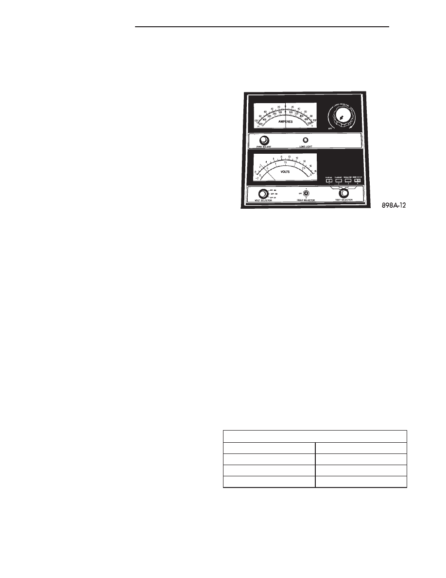
(1) Measure the voltage at the battery posts with a

voltmeter, accurate to 1/10 (0.10) volt (Fig. 7). If the
reading is below ten volts, the battery charging cur-

rent will be low. It could take some time before the
battery accepts a current greater than a few milliam-
peres. Such low current may not be detectable on the
ammeters built into many battery chargers.

(2) Disconnect and isolate the battery negative

cable. Connect the battery charger leads. Some bat-
tery chargers are equipped with polarity-sensing cir-
cuitry. This circuitry protects the battery charger and
the battery from being damaged if they are improp-
erly connected. If the battery state-of-charge is too
low for the polarity-sensing circuitry to detect, the
battery charger will not operate. This makes it
appear that the battery will not accept charging cur-
rent. See the instructions provided by the manufac-
turer of the battery charger for details on how to
bypass the polarity-sensing circuitry.

(3) Battery chargers vary in the amount of voltage

and current they provide. The amount of time
required for a battery to accept measurable charging
current at various voltages is shown in the Charge
Rate Table. If the charging current is still not mea-
surable at the end of the charging time, the battery
is faulty and must be replaced. If the charging cur-
rent is measurable during the charging time, the bat-
tery may be good and the charging should be
completed in the normal manner.

CHARGE RATE TABLE

Voltage

Hours

16.0 volts maximum

up to 4 hours

14.0 to 15.9 volts

up to 8 hours

13.9 volts or less

up to 16 hours

CHARGING TIME REQUIRED

The time required to charge a battery will vary,

depending upon the following factors:

• Battery Capacity - A completely discharged

heavy-duty battery requires twice the charging time
of a small capacity battery.

Fig. 7 Voltmeter - Typical

8F - 10

BATTERY SYSTEM

AN

BATTERY (Continued)

• Temperature - A longer time will be needed to

charge a battery at -18° C (0° F) than at 27° C (80°
F). When a fast battery charger is connected to a cold
battery, the current accepted by the battery will be
very low at first. As the battery warms, it will accept
a higher charging current rate (amperage).

• Charger Capacity - A battery charger that

supplies only five amperes will require a longer
charging time. A battery charger that supplies
twenty amperes or more will require a shorter charg-
ing time.

• State-Of-Charge - A completely discharged bat-

tery requires more charging time than a partially
discharged battery. Electrolyte is nearly pure water
in a completely discharged battery. At first, the
charging current (amperage) will be low. As the bat-
tery charges, the specific gravity of the electrolyte
will gradually rise.

The Battery Charging Time Table gives an indica-

tion of the time required to charge a typical battery
at room temperature based upon the battery state-of-
charge and the charger capacity.

BATTERY CHARGING TIME TABLE

Charging

Amperage

5 Amps

10

Amps

20 Amps

Open Circuit

Voltage

Hours Charging @ 21° C (70°

F)

12.25 to 12.49

6 hours

3 hours

1.5

hours

12.00 to 12.24

10 hours

5 hours

2.5

hours

10.00 to 11.99

14 hours

7 hours

3.5

hours

Below 10.00

18 hours

9 hours

4.5

hours

STANDARD PROCEDURE - BUILT-IN
INDICATOR TEST

An indicator (hydrometer) built into the top of the

battery case provides visual information for battery
testing (Fig. 8). Like a hydrometer, the built-in indi-
cator measures the specific gravity of the battery
electrolyte. The specific gravity of the electrolyte
reveals the battery state-of-charge; however, it will
not reveal the cranking capacity of the battery. A load
test must be performed to determine the battery
cranking capacity. Refer to Standard Procedures for
the proper battery load test procedures.

WARNING: IF THE BATTERY SHOWS SIGNS OF
FREEZING, LEAKING OR LOOSE POSTS, DO NOT
TEST, ASSIST-BOOST, OR CHARGE. THE BATTERY

MAY ARC INTERNALLY AND EXPLODE. PERSONAL
INJURY AND/OR VEHICLE DAMAGE MAY RESULT.

WARNING: EXPLOSIVE HYDROGEN GAS FORMS IN
AND AROUND THE BATTERY. DO NOT SMOKE,
USE FLAME, OR CREATE SPARKS NEAR THE BAT-
TERY. PERSONAL INJURY AND/OR VEHICLE DAM-
AGE MAY RESULT.

WARNING: THE BATTERY CONTAINS SULFURIC
ACID, WHICH IS POISONOUS AND CAUSTIC. AVOID
CONTACT WITH THE SKIN, EYES, OR CLOTHING.
IN THE EVENT OF CONTACT, FLUSH WITH WATER
AND CALL A PHYSICIAN IMMEDIATELY. KEEP OUT
OF THE REACH OF CHILDREN.

WARNING: IF THE BATTERY IS EQUIPPED WITH
REMOVABLE CELL CAPS, BE CERTAIN THAT EACH
OF THE CELL CAPS IS IN PLACE AND TIGHT
BEFORE THE BATTERY IS RETURNED TO SER-
VICE. PERSONAL INJURY AND/OR VEHICLE DAM-
AGE MAY RESULT FROM LOOSE OR MISSING
CELL CAPS.

Before testing, visually inspect the battery for any

damage (a cracked case or cover, loose posts, etc.)
that would cause the battery to be faulty. In order to
obtain correct indications from the built-in indicator,
it is important that the battery be level and have a
clean sight glass. Additional light may be required to
view the indicator. Do not use open flame as a
source of additional light.

To read the built-in indicator, look into the sight

glass and note the color of the indication (Fig. 9). The
battery

condition

that

each

color

indicates

is

described in the following list:

Fig. 8 Built-In Indicator

1 - SIGHT GLASS
2 - BATTERY TOP
3 - GREEN BALL
4 - PLASTIC ROD

AN

BATTERY SYSTEM

8F - 11

BATTERY (Continued)

• Green - Indicates 75% to 100% battery state-of-

charge. The battery is adequately charged for further
testing or return to service. If the starter will not
crank for a minimum of fifteen seconds with a fully-
charged battery, the battery must be load tested.
Refer to Standard Procedures for the proper battery
load test procedures.

• Black or Dark - Indicates 0% to 75% battery

state-of-charge. The battery is inadequately charged
and must be charged until a green indication is visi-
ble in the sight glass (12.4 volts or more), before the
battery is tested further or returned to service. Refer
to Standard Procedures for the proper battery charg-
ing procedures. Also refer to Diagnosis and Testing
for more information on the possible causes of the
discharged battery condition.

• Clear or Bright - Indicates a low battery elec-

trolyte level. The electrolyte level in the battery is
below the built-in indicator. A maintenance-free bat-
tery with non-removable cell caps must be replaced if
the electrolyte level is low. Water must be added to a
low-maintenance battery with removable cell caps
before it is charged. Refer to Standard Procedures for
the proper battery filling procedures. A low electro-
lyte level may be caused by an overcharging condi-
tion. Refer to Charging System for the proper
charging system diagnosis and testing procedures.

STANDARD PROCEDURE - HYDROMETER TEST

The hydrometer test reveals the battery state-of-

charge by measuring the specific gravity of the elec-
trolyte.

This

test

cannot

be

performed

on

maintenance-free batteries with non-removable
cell caps. 
If the battery has non-removable cell caps,
refer to Diagnosis and Testing for alternate methods
of determining the battery state-of-charge.

Specific gravity is a comparison of the density of

the battery electrolyte to the density of pure water.
Pure water has a specific gravity of 1.000, and sulfu-
ric acid has a specific gravity of 1.835. Sulfuric acid
makes up approximately 35% of the battery electro-
lyte by weight, or 24% by volume. In a fully-charged

battery the electrolyte will have a temperature-cor-
rected specific gravity of 1.260 to 1.290. However, a
specific gravity of 1.235 or above is satisfactory for
the battery to be load tested and/or returned to ser-
vice.

WARNING: IF THE BATTERY SHOWS SIGNS OF
FREEZING, LEAKING OR LOOSE POSTS, DO NOT
TEST, ASSIST-BOOST, OR CHARGE. THE BATTERY
MAY ARC INTERNALLY AND EXPLODE. PERSONAL
INJURY AND/OR VEHICLE DAMAGE MAY RESULT.

WARNING: EXPLOSIVE HYDROGEN GAS FORMS IN
AND AROUND THE BATTERY. DO NOT SMOKE,
USE FLAME, OR CREATE SPARKS NEAR THE BAT-
TERY. PERSONAL INJURY AND/OR VEHICLE DAM-
AGE MAY RESULT.

WARNING: THE BATTERY CONTAINS SULFURIC
ACID, WHICH IS POISONOUS AND CAUSTIC. AVOID
CONTACT WITH THE SKIN, EYES, OR CLOTHING.
IN THE EVENT OF CONTACT, FLUSH WITH WATER
AND CALL A PHYSICIAN IMMEDIATELY. KEEP OUT
OF THE REACH OF CHILDREN.

WARNING: IF THE BATTERY IS EQUIPPED WITH
REMOVABLE CELL CAPS, BE CERTAIN THAT EACH
OF THE CELL CAPS IS IN PLACE AND TIGHT
BEFORE THE BATTERY IS RETURNED TO SER-
VICE. PERSONAL INJURY AND/OR VEHICLE DAM-
AGE MAY RESULT FROM LOOSE OR MISSING
CELL CAPS.

Before testing, visually inspect the battery for any

damage (a cracked case or cover, loose posts, etc.)
that would cause the battery to be faulty. Then
remove the battery cell caps and check the electrolyte
level. Add distilled water if the electrolyte level is
below the top of the battery plates. Refer to Battery
System Cleaning for the proper battery inspection
procedures.

See the instructions provided by the manufacturer

of the hydrometer for recommendations on the cor-
rect use of the hydrometer that you are using.
Remove only enough electrolyte from the battery cell
so that the float is off the bottom of the hydrometer
barrel with pressure on the bulb released. To read
the hydrometer correctly, hold it with the top surface
of the electrolyte at eye level (Fig. 10).

CAUTION: Exercise care when inserting the tip of
the hydrometer into a battery cell to avoid damag-
ing the plate separators. Damaged plate separators
can cause early battery failure.

Fig. 9 Built-In Indicator Sight Glass Chart

8F - 12

BATTERY SYSTEM

AN

BATTERY (Continued)

Hydrometer floats are generally calibrated to indi-

cate the specific gravity correctly only at 26.7° C (80°
F). When testing the specific gravity at any other
temperature, a correction factor is required. The cor-
rection factor is approximately a specific gravity
value of 0.004, which may also be identified as four
points of specific gravity. For each 5.5° C above 26.7°
C (10° F above 80° F), add four points. For each 5.5°
C below 26.7° C (10° F below 80° F), subtract four
points. Always correct the specific gravity for temper-
ature variation.

EXAMPLE: A battery is tested at -12.2° C (10° F)

and has a specific gravity of 1.240. Determine the
actual specific gravity as follows:

(1) Determine the number of degrees above or

below 26.7° C (80° F):

26.6° C - -12.2° C = 38.8° C

(80° F - 10° F = 70° F)

(2) Divide the result from Step 1 by 5.5° C (10°

F):

38.8° C

5.5° C = 7 (70° F 10° F = 7)

(3) Multiply the result from Step 2 by the temper-

ature correction factor (0.004):

7 X 0.004 = 0.028

(4) The temperature at testing was below 26.7° C

(80° F); therefore, the temperature correction factor
is subtracted:

1.240 - 0.028 = 1.212

(5) The corrected specific gravity of the battery cell

in this example is 1.212.

Test the specific gravity of the electrolyte in each

battery cell. If the specific gravity of all cells is above
1.235, but the variation between cells is more than
fifty points (0.050), the battery should be replaced. If
the specific gravity of one or more cells is less than
1.235, charge the battery at a rate of approximately
five amperes. Continue charging the battery until
three consecutive specific gravity tests, taken at one-
hour intervals, are constant. If the cell specific grav-
ity variation is more than fifty points (0.050) at the
end of the charge period, replace the battery.

When the specific gravity of all cells is above 1.235,

and the cell variation is less than fifty points (0.050),
the battery may be load tested to determine its
cranking capacity. Refer to Standard Procedures for
the proper battery load test procedures.

STANDARD PROCEDURE - OPEN-CIRCUIT
VOLTAGE TEST

A battery open-circuit voltage (no load) test will

show the approximate state-of-charge of a battery.
This test can be used in place of the hydrometer test
when a hydrometer is not available, or for mainte-
nance-free batteries with non-removable cell caps.

WARNING: IF THE BATTERY SHOWS SIGNS OF
FREEZING, LEAKING OR LOOSE POSTS, DO NOT
TEST, ASSIST-BOOST, OR CHARGE. THE BATTERY
MAY ARC INTERNALLY AND EXPLODE. PERSONAL
INJURY AND/OR VEHICLE DAMAGE MAY RESULT.

WARNING: EXPLOSIVE HYDROGEN GAS FORMS IN
AND AROUND THE BATTERY. DO NOT SMOKE,
USE FLAME, OR CREATE SPARKS NEAR THE BAT-
TERY. PERSONAL INJURY AND/OR VEHICLE DAM-
AGE MAY RESULT.

WARNING: THE BATTERY CONTAINS SULFURIC
ACID, WHICH IS POISONOUS AND CAUSTIC. AVOID
CONTACT WITH THE SKIN, EYES, OR CLOTHING.
IN THE EVENT OF CONTACT, FLUSH WITH WATER
AND CALL A PHYSICIAN IMMEDIATELY. KEEP OUT
OF THE REACH OF CHILDREN.

WARNING: IF THE BATTERY IS EQUIPPED WITH
REMOVABLE CELL CAPS, BE CERTAIN THAT EACH
OF THE CELL CAPS IS IN PLACE AND TIGHT
BEFORE THE BATTERY IS RETURNED TO SER-
VICE. PERSONAL INJURY AND/OR VEHICLE DAM-
AGE MAY RESULT FROM LOOSE OR MISSING
CELL CAPS.

Fig. 10 Hydrometer - Typical

1 - BULB
2 - SURFACE COHESION
3 - SPECIFIC GRAVITY READING
4 - TEMPERATURE READING
5 - HYDROMETER BARREL
6 - FLOAT

AN

BATTERY SYSTEM

8F - 13

BATTERY (Continued)


Content   ..  295  296  297  298   ..