Dodge Dakota (R1). Manual - part 238


  Index      Dodge     Dodge Dakota (R1) - service repair manual 2000 year


Search            


Content   ..  236  237  238  239   ..


Dodge Dakota (R1). Manual - part 238


INSPECTION

Inspect the cylinder bore. Light discoloration and

dark stains in the bore are normal and will not
impair cylinder operation.

The cylinder bore can be lightly polished but only

with crocus cloth. Replace the cylinder if the bore is
scored, pitted or heavily corroded. Honing the bore to
restore the surface is not recommended.

Inspect the cylinder pistons. The piston surfaces

should be smooth and free of scratches, scoring and
corrosion. Replace the pistons if worn, scored, or cor-
roded. Do attempt to restore the surface by sanding
or polishing.

Discard the old piston cups and the spring and

expander. These parts are not reusable. The original
dust boots may be reused but only if they are in good
condition.

ASSEMBLY

(1) Lubricate wheel cylinder bore, pistons, piston

cups and spring and expander with clean brake fluid.

(2) Install first piston in cylinder bore. Then

install first cup in bore and against piston. Be sure
lip of piston cup is facing inward (toward
spring and expander) and flat side is against
piston.

(3) Install

spring

and

expander

followed

by

remaining piston cup and piston.

(4) Install boots on each end of cylinder and insert

push rods in boots.

(5) Install cylinder bleed screw.

INSTALLATION

(1) Apply bead of silicone sealer around cylinder

mounting surface of support plate.

(2) Install cylinder mounting bolts and tighten to

20 N·m (15 ft. lbs.).

(3) Connect brake line to cylinder.
(4) Install brake shoe return spring.
(5) Install brake drum.
(6) Install wheel and tire assembly. (Refer to 22 -

TIRES/WHEELS/WHEELS - STANDARD PROCE-
DURE).

(7) Bleed base brake system. (Refer to 5 - BRAKES

- STANDARD PROCEDURE).

SUPPORT PLATE

REMOVAL

(1) Remove wheel and tire assembly and brake

drum.

(2) Remove brake shoe assembly. (Refer to 5 -

BRAKES/HYDRAULIC/MECHANICAL/DRUM

-

REMOVAL).

(3) Remove parking brake cable from parking

brake

lever.

(Refer

to

5

-

BRAKES/PARKING

BRAKE/CABLES - REMOVAL).

(4) Compress parking brake cable retainer tabs.

Then push retainer and cable through and out of
support plate.

(5) Disconnect brake line at wheel cylinder.
(6) Remove wheel cylinder from support plate.

(Refer to 5 - BRAKES/HYDRAULIC/MECHANICAL/
WHEEL CYLINDERS - REMOVAL).

(7) Remove axle shaft, (Refer to 3 - DIFFEREN-

TIAL & DRIVELINE/REAR AXLE - 9 1/4/AXLE
SHAFTS - REMOVAL).

(8) Remove bolts attaching support plate to axle

and remove support plate.

INSTALLATION

(1) Apply bead of silicone sealer around axle

mounting surface of support plate.

(2) Install support plate on axle flange. Tighten

attaching bolts to 115 N·m (85 ft. lbs.).

(3) Apply bead of silicone sealer around wheel cyl-

inder mounting surface and install wheel cylinder.
(Refer to 5 - BRAKES/HYDRAULIC/MECHANICAL/
WHEEL CYLINDERS - INSTALLATION).

(4) Install brake line in wheel cylinder.
(5) Install parking brake cable in support plate.
(6) Install axle shaft, (Refer to 3 - DIFFEREN-

TIAL & DRIVELINE/REAR AXLE - 9 1/4/AXLE
SHAFTS - INSTALLATION).

(7) Connect parking brake cable to lever on sec-

ondary shoe and install brake shoes on support plate.

(8) Adjust brake shoes to drum with brake gauge.

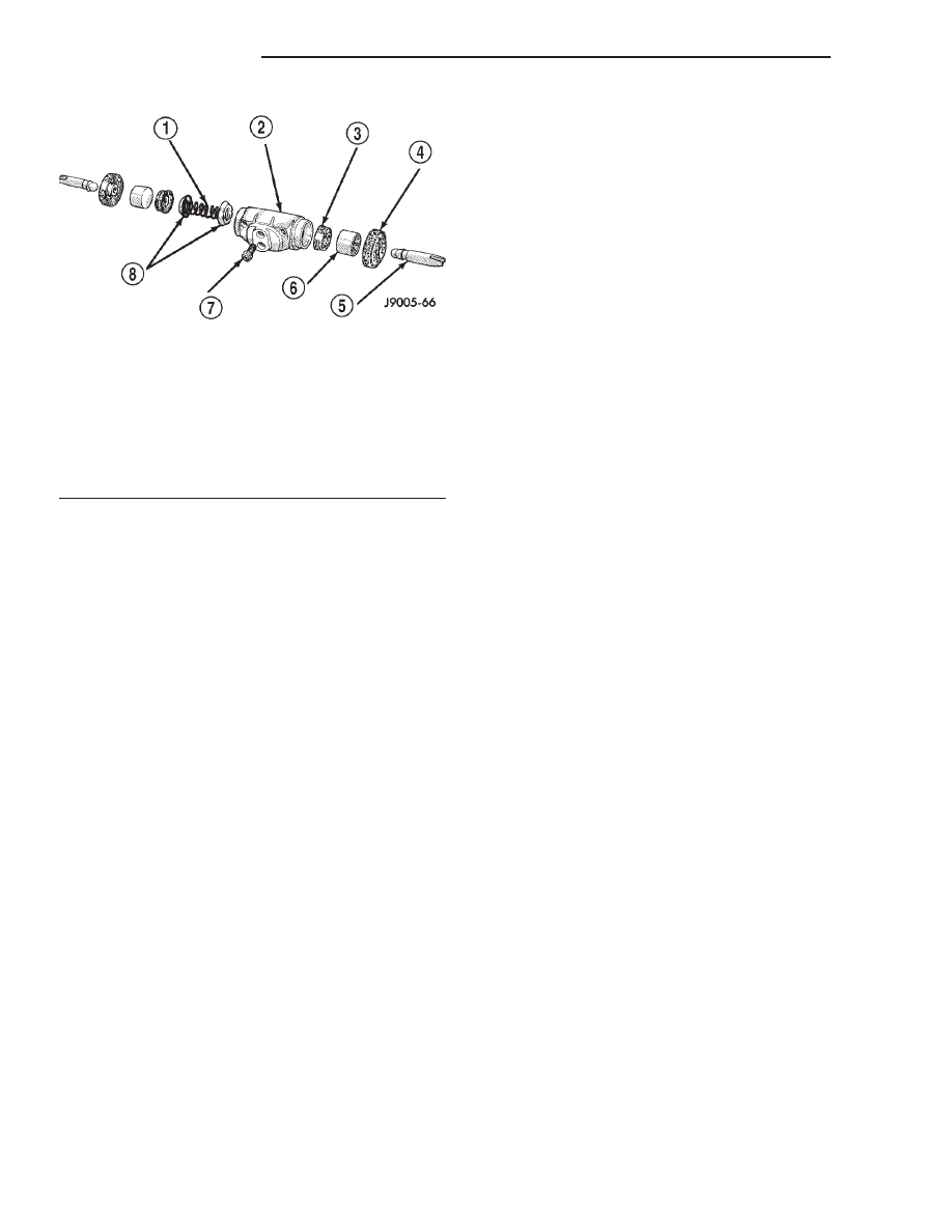
Fig. 48 Wheel Cylinder Components–Typical

1 - SPRING
2 - CYLINDER
3 - PISTON CLIP
4 - BOOT
5 - PUSH ROD
6 - PISTON
7 - BLEED SCREW
8 - CUP EXPANDERS

5 - 28

BRAKES - BASE

AN

WHEEL CYLINDERS (Continued)

(9) Install brake drum and wheel and tire assem-

bly. (Refer to 22 - TIRES/WHEELS/WHEELS -
STANDARD PROCEDURE) (Refer to 22 - TIRES/
WHEELS/WHEELS - STANDARD PROCEDURE).

(10) Bleed brake system. (Refer to 5 - BRAKES -

STANDARD PROCEDURE).

CABLES

REMOVAL - FRONT PARK BRAKE CABLE

(1) Raise and support the vehicle.
(2) Loosen cable adjusting nut.
(3) Disengage front cable (Fig. 49) from cable ten-

sioner.

(4) Remove support cable from the front cable (Fig.

50).

(5) Remove support and lower vehicle.
(6) Remove left kick panel.
(7) Fold left front edge of floor covering rearward

and remove cable grommet from floor pan (Fig. 50).

(8) Remove cable from park brake pedal assembly.

(Refer to 5 - BRAKES/PARKING BRAKE/PEDAL -
REMOVAL).

(9) Work cable and housing assembly up through

floor pan.

(10) Remove front cable from vehicle.

REMOVAL - REAR PARK BRAKE CABLES

(1) Raise and support the vehicle.
(2) Remove the rear wheel and tire assemblies.
(3) Loosen tensioner adjuster nut.
(4) Remove the right cable (Fig. 51) from the

extension cable.

(5) Remove the right cable from the frame clip and

pull the cable housing through the left cable connec-
tor.

(6) Remove the left cable connector from the left

cable.

(7) Pull both cables (Fig. 51) through the cable

bracket.

(8) Remove the right cable mounting retainers

from the from the differential housing.

(9) Remove the brake drums.
(10) Disconnect each cable from park brake lever.
(11) Compress tabs on each cable housing retainer

at the brake support plate.

(12) Remove the cables from the brake support

plates.

INSTALLATION - FRONT PARK BRAKE CABLE

(1) Insert front cable through floor pan and install

grommet.

(2) Insert cable retainer into hole at bottom of

pedal assembly bracket and connect cable end.

(3) Fold floor covering down and install kick panel.
(4) Raise and support vehicle.
(5) Install support cable to the front cable.
(6) Attach front cable to tensioner.
(7) Adjust parking brakes.
(8) Remove support and lower vehicle.

INSTALLATION - REAR PARK BRAKE CABLES

(1) Push each cable housing through the brake

support plate hole until cable housing retainer tabs
lock into place.

NOTE: Pull on the cable housing to ensure it is lock
into place.

Fig. 49 Front Cable & Tensioner

1 - TENSIONER
2 - ADJUSTER NUT
3 - FRONT CABLE

Fig. 50 Support Cable

1 - GROMMET
2 - SUPPORT CABLE
3 - FRONT CABLE

AN

BRAKES - BASE

5 - 29

SUPPORT PLATE (Continued)

(2) Pull back on the end of the cable. Then push

the cable in to engage the cable in the park brake
lever.

NOTE: Pull on the cable end to ensure it is attached
it the park brake lever.

(3) Install the brake drums.
(4) Install right cable mounting retainers.
(5) Push the cables housing through the cable

bracket.

(6) Install the left cable onto the cable connector.
(7) Push the right cable housing through the left

cable connector and connect the cable to the exten-
sion cable.

(8) Install the wheel and tire assemblies. (Refer to

22 - TIRES/WHEELS/WHEELS - STANDARD PRO-
CEDURE).

(9) Perform park brake adjustment procedure.

(Refer to 5 - BRAKES/PARKING BRAKE/CABLES -
ADJUSTMENTS).

(10) Remove support and lower the vehicle.

PARK BRAKE CABLE TENSIONER

NOTE: Tensioner adjustment is only necessary
when the tensioner, or a cable has been replaced or
disconnected for service. When adjustment is nec-
essary, perform adjustment only as described in the
following procedure. This is necessary to avoid
faulty park brake operation.

(1) Raise vehicle.
(2) Back off cable tensioner adjusting nut at equal-

izer to create slack in cables.

(3) Remove

rear

wheel/tire

assemblies.

Then

remove brake drums.

(4) Verify brakes are in good condition and operat-

ing properly.

(5) Verify park brake cables operate freely and are

not binding, or seized.

(6) Check rear brake shoe adjustment with stan-

dard brake gauge.

(7) Install drums and verify that drums rotate

freely without drag.

(8) Reinstall wheel/tire assemblies after brake

shoe adjustment is complete.

(9) Lower vehicle enough for access to park brake

foot pedal. Then fully apply park brakes.

NOTE: Leave park brakes applied until adjustment
is complete.

(10) Raise vehicle again.
(11) Mark tensioner rod 6.35 mm (1/4 in.) from

edge of tensioner bracket (Fig. 52).

(12) Tighten adjusting nut at equalizer until mark

on tensioner rod moves into alignment with tensioner
bracket.

CAUTION: Do not loosen, or tighten the tensioner
adjusting nut for any reason after completing
adjustment.

(13) Lower vehicle until rear wheels are 15-20 cm

(6-8 in.) off shop floor.

(14) Release park brake foot pedal and verify that

rear wheels rotate freely without drag. Then lower
vehicle.

PEDAL

DESCRIPTION

The rear drum brake shoes serve as the parking

brakes. The parking brakes are operated by a system
of cables and levers attached to the rear brake sec-
ondary shoes.

Fig. 51 Park Brake Cables

1 - CABLE RETAINERS
2 - LEFT CABLE
3 - LEFT CABLE CONNECTOR
4 - EXTENSION CABLE
5 - TENSIONER
6 - FRONT CABLE
7 - FRAME CLIPS
8 - CABLE BRACKET
9 - RIGHT CABLE

5 - 30

BRAKES - BASE

AN

CABLES (Continued)

OPERATION

The shoes make contact with the brake drum sur-

face by a cable and lever mechanism attached to the
secondary brake shoe. The front parking brake cable
is connected to the parking brake pedal and to the
rear cables. An intermediate cable is used on some
vehicles to connect the front and rear cables.

The parking brake pedal assembly is mounted on

the driver side cowl panel. The front cable is directly
attached to the assembly. The pedal assembly con-
tains a spring loaded mechanism to hold the pedal in
the applied position. A rod and spring are used to
release the ratchet mechanism and return the pedal
to normal position.

REMOVAL

(1) Remove left side kick panel.
(2) Remove brake release rod from pedal assembly

(Fig. 53).

(3) Disconnect brake warning lamp switch.
(4) Remove front parking brake cable. (Refer to 5 -

BRAKES/PARKING BRAKE/CABLES - REMOVAL).

(5) Remove mounting nuts and mounting bolt.
(6) Slide assembly rearward off the mounting

studs (Fig. 53).

INSTALLATION

(1) Install assembly on the mounting studs.
(2) Install mounting bolt and nuts.
(3) Install front parking brake cable. (Refer to 5 -

BRAKES/PARKING BRAKE/CABLES - INSTALLA-
TION).

(4) Connect brake warning lamp switch.
(5) Install brake release rod to pedal assembly.
(6) Install left side kick panel.

RELEASE

REMOVAL

WARNING: ON VEHICLES EQUIPPED WITH AIR-
BAGS, REFER TO - PASSIVE RESTRAINT SYSTEMS
BEFORE ATTEMPTING ANY STEERING WHEEL,
STEERING

COLUMN,

OR

INSTRUMENT

PANEL

COMPONENT DIAGNOSIS OR SERVICE. FAILURE
TO TAKE THE PROPER PRECAUTIONS COULD
RESULT IN ACCIDENTAL AIRBAG DEPLOYMENT
AND POSSIBLE PERSONAL INJURY.

(1) Disconnect and isolate the battery negative

cable.

(2) Reach under the driver side outboard end of

the instrument panel to access and unsnap the plas-
tic retainer clip that secures the park brake release
linkage rod to the lever on the back side of the park
brake release handle.

(3) Disengage the park brake release linkage rod

end from the lever on the back of the park brake
release handle.

(4) Using a trim stick or another suitable wide

flat-bladed tool, gently pry one of the park brake
handle hinge tabs away from its pivot pin on the
instrument panel (Fig. 54).

(5) While prying the park brake release handle

hinge tab with one hand, use the other hand to pull
the handle firmly down and away from the pivot pin.

(6) Remove the park brake release handle from the

instrument panel.

Fig. 52 Adjustment Mark On Cable Tensioner Rod

1 - CABLE CONNECTOR
2 - ADJUSTER NUT
3 - 6.35MM

(1/4 IN.)

Fig. 53 Parking Brake Pedal Assembly

1 - PARKING BRAKE ASSEMBLY
2 - LEFT COWL PANEL
3 - FRONT CABLE
4 - RELEASE ROD

AN

BRAKES - BASE

5 - 31

PEDAL (Continued)


Content   ..  236  237  238  239   ..