Dodge Dakota (R1). Manual - part 236


  Index      Dodge     Dodge Dakota (R1) - service repair manual 2000 year


Search            


Content   ..  234  235  236  237   ..


Dodge Dakota (R1). Manual - part 236


(17) Install wheel and tire assembly. (Refer to 22 -

TIRES/WHEELS/WHEELS - STANDARD PROCE-
DURE).

ADJUSTMENTS - REAR DRUM BRAKE

The rear drum brakes are equipped with a self-ad-

justing mechanism. Under normal circumstances, the
only time adjustment is required is when the shoes
are replaced, removed for access to other parts, or
when one or both drums are replaced.

Adjustment can be made with a standard brake

gauge or with adjusting tool. Adjustment is per-
formed with the complete brake assembly installed
on the backing plate.

ADJUSTMENT WITH BRAKE GAUGE

(1) Be sure parking brakes are fully released.
(2) Raise rear of vehicle and remove wheels and

brake drums.

(3) Verify that left and right automatic adjuster

levers and cables are properly connected.

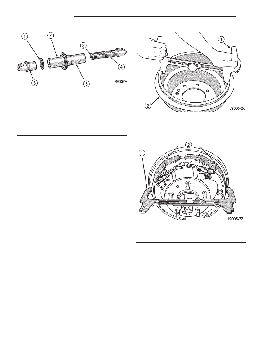
(4) Insert brake gauge in drum. Expand gauge

until gauge inner legs contact drum braking surface.
Then lock gauge in position (Fig. 31).

(5) Reverse gauge and install it on brake shoes.

Position gauge legs at shoe centers as shown (Fig.
32). If gauge does not fit (too loose/too tight), adjust
shoes.

(6) Pull shoe adjuster lever away from adjuster

screw star wheel.

(7) Turn adjuster screw star wheel (by hand) to

expand or retract brake shoes. Continue adjustment
until gauge outside legs are light drag-fit on shoes.

(8) Install brake drums and wheels and lower

vehicle.

(9) Drive vehicle and make one forward stop fol-

lowed by one reverse stop. Repeat procedure 8-10
times to operate automatic adjusters and equalize
adjustment.

NOTE: Bring vehicle to complete standstill at each
stop. Incomplete, rolling stops will not activate
automatic adjusters.

ADJUSTMENT WITH ADJUSTING TOOL

(1) Be sure parking brake lever is fully released.
(2) Raise vehicle so rear wheels can be rotated

freely.

(3) Remove plug from each access hole in brake

support plates.

Fig. 30 Adjuster Screw

1 - WASHER
2 - SOCKET
3 - STAMPED LETTER

L-LEFT BRAKE
R-RIGHT BRAKE

4 - SCREW THREADS
5 - NUT
6 - BUTTON

Fig. 31 Adjusting Gauge On Drum

1 - BRAKE GAUGE
2 - BRAKE DRUM

Fig. 32 Adjusting Gauge On Brake Shoes

1 - BRAKE GAUGE
2 - BRAKE SHOES

5 - 20

BRAKES - BASE

AN

DRUM (Continued)

(4) Loosen parking brake cable adjustment nut

until there is slack in front cable.

(5) Insert adjusting tool through support plate

access hole and engage tool in teeth of adjusting
screw star wheel (Fig. 33).

(6) Rotate adjuster screw star wheel (move tool

handle upward) until slight drag can be felt when
wheel is rotated.

(7) Push and hold adjuster lever away from star

wheel with thin screwdriver.

(8) Back off adjuster screw star wheel until brake

drag is eliminated.

(9) Repeat adjustment at opposite wheel. Be sure

adjustment is equal at both wheels.

(10) Install support plate access hole plugs.
(11) Adjust parking brake cable and lower vehicle.
(12) Drive vehicle and make one forward stop fol-

lowed by one reverse stop. Repeat procedure 8-10
times to operate automatic adjusters and equalize
adjustment.

NOTE: Bring vehicle to complete standstill at each
stop. Incomplete, rolling stops will not activate
automatic adjusters.

FLUID

DIAGNOSIS AND TESTING - BRAKE FLUID
CONTAMINATION

Indications of fluid contamination are swollen or

deteriorated rubber parts.

Swollen rubber parts indicate the presence of

petroleum in the brake fluid.

To test for contamination, put a small amount of

drained brake fluid in clear glass jar. If fluid sepa-
rates into layers, there is mineral oil or other fluid
contamination of the brake fluid.

If brake fluid is contaminated, drain and thor-

oughly flush system. Replace master cylinder, propor-
tioning valve, caliper seals, wheel cylinder seals,
Antilock Brakes hydraulic unit and all hydraulic
fluid hoses.

SPECIFICATIONS

BRAKE FLUID

The brake fluid used in this vehicle must conform

to DOT 3 specifications and SAE J1703 standards.
No other type of brake fluid is recommended or
approved for usage in the vehicle brake system. Use
only Mopar brake fluid or an equivalent from a
tightly sealed container.

CAUTION: Never use reclaimed brake fluid or fluid
from an container which has been left open. An
open container of brake fluid will absorb moisture
from the air and contaminate the fluid.

CAUTION: Never use any type of a petroleum-based
fluid in the brake hydraulic system. Use of such
type fluids will result in seal damage of the vehicle
brake hydraulic system causing a failure of the
vehicle brake system. Petroleum based fluids would
be items such as engine oil, transmission fluid,
power steering fluid, etc.

FLUID RESERVOIR

REMOVAL

(1) Remove reservoir cap and empty fluid into

drain container.

(2) Clamp cylinder body in vise with brass protec-

tive jaws.

(3) Remove pins that retain reservoir to master

cylinder. Use hammer and pin punch to remove pins
(Fig. 34).

(4) Loosen reservoir from grommets with pry tool

(Fig. 35).

Fig. 33 Brake Adjustment

1 - STAR WHEEL
2 - LEVER
3 - BRAKE SHOE WEB
4 - SCREWDRIVER
5 - ADJUSTING TOOL
6 - ADJUSTER SPRING

AN

BRAKES - BASE

5 - 21

DRUM (Continued)

(5) Remove reservoir by rocking it to one side and

pulling free of grommets (Fig. 36).

(6) Remove old grommets from cylinder body (Fig.

37).

INSTALLATION

CAUTION: Do not use any type of tool to install the
grommets. Tools may cut, or tear the grommets cre-
ating a leak problem after installation. Install the
grommets using finger pressure only.

(1) Lubricate new grommets with clean brake fluid

and Install new grommets in cylinder body (Fig. 38).
Use finger pressure to install and seat grommets.

Fig. 34 Reservoir Retaining Pins

1 - PIN PUNCH
2 - RESERVOIR
3 - BODY
4 - ROLL PINS

Fig. 35 Loosening Reservoir

1 - PRY TOOL
2 - RESERVOIR
3 - GROMMET
4 - MASTER CYLINDER BODY

Fig. 36 Reservoir Removal

1 - RESERVOIR
2 - GROMMETS

Fig. 37 Grommet Removal

1 - MASTER CYLINDER BODY
2 - GROMMETS

Fig. 38 Grommet Installation

1 - WORK NEW GROMMETS INTO PLACE USING FINGER

PRESSURE ONLY

5 - 22

BRAKES - BASE

AN

FLUID RESERVOIR (Continued)

(2) Start reservoir in grommets. Then rock reser-

voir back and forth while pressing downward to seat
it in grommets.

(3) Install pins that retain reservoir to cylinder

body.

(4) Fill and bleed master cylinder on bench before

installation in vehicle.

MASTER CYLINDER

DESCRIPTION

A two-piece master cylinder is used on all models.

The cylinder body containing the primary and sec-
ondary pistons is made of aluminum. The removable
fluid reservoir is made of nylon reinforced with glass
fiber. The reservoir stores reserve brake fluid for the
hydraulic brake circuits. The reservoir is the only
serviceable component.

The fluid compartments of the nylon reservoir are

interconnected to permit fluid level equalization.
However, the equalization feature does not affect cir-
cuit separation in the event of a front or rear brake
malfunction. The reservoir compartments will retain
enough fluid to operate the functioning hydraulic cir-
cuit.

Care must be exercised when removing/installing

the master cylinder connecting lines. The threads in
the cylinder fluid ports can be damaged if care is not
exercised. Start all brake line fittings by hand to
avoid cross threading.

The cylinder reservoir can be replaced when neces-

sary. However, the aluminum body section of the
master cylinder is not a repairable component.

NOTE: If diagnosis indicates that an internal mal-
function has occurred, the aluminum body section
must be replaced as an assembly.

OPERATION

The master cylinder bore contains a primary and

secondary

piston.

The

primary

piston

supplies

hydraulic pressure to the front brakes. The secondary
piston supplies hydraulic pressure to the rear brakes.

DIAGNOSIS AND TESTING - MASTER
CYLINDER/POWER BOOSTER

(1) Start engine and check booster vacuum hose

connections. A hissing noise indicates vacuum leak.
Correct any vacuum leak before proceeding.

(2) Stop engine and shift transmission into Neu-

tral.

(3) Pump brake pedal until all vacuum reserve in

booster is depleted.

(4) Press and hold brake pedal under light foot

pressure. The pedal should hold firm, if the pedal
falls away master cylinder is faulty (internal leak-
age).

(5) Start engine and note pedal action. It should

fall away slightly under light foot pressure then hold
firm. If no pedal action is discernible, power booster,
vacuum supply, or vacuum check valve is faulty. Pro-
ceed to the POWER BOOSTER VACUUM TEST.

(6) If the POWER BOOSTER VACUUM TEST

passes, rebuild booster vacuum reserve as follows:
Release brake pedal. Increase engine speed to 1500
rpm, close the throttle and immediately turn off igni-
tion to stop engine.

(7) Wait a minimum of 90 seconds and try brake

action again. Booster should provide two or more vac-
uum assisted pedal applications. If vacuum assist is
not provided, booster is faulty.

POWER BOOSTER VACUUM TEST

(1) Connect vacuum gauge to booster check valve

with short length of hose and T-fitting (Fig. 39).

(2) Start and run engine at curb idle speed for one

minute.

(3) Observe the vacuum supply. If vacuum supply

is not adequate, repair vacuum supply.

(4) Clamp hose shut between vacuum source and

check valve.

(5) Stop engine and observe vacuum gauge.
(6) If vacuum drops more than one inch HG (33

millibars) within 15 seconds, booster diaphragm or
check valve is faulty.

POWER BOOSTER CHECK VALVE TEST

(1) Disconnect vacuum hose from check valve.
(2) Remove check valve and valve seal from

booster.

(3) Use a hand operated vacuum pump for test.
(4) Apply 15-20 inches vacuum at large end of

check valve (Fig. 40).

(5) Vacuum should hold steady. If gauge on pump

indicates vacuum loss, check valve is faulty and
should be replaced.

STANDARD PROCEDURE - MASTER CYLINDER
BLEEDING

A new master cylinder should be bled before instal-

lation on the vehicle. Required bleeding tools include
bleed tubes and a wood dowel to stroke the pistons.
Bleed tubes can be fabricated from brake line.

(1) Mount master cylinder in vise.
(2) Attach bleed tubes to cylinder outlet ports.

Then position each tube end into reservoir (Fig. 41).

(3) Fill reservoir with fresh brake fluid.
(4) Press cylinder pistons inward with wood dowel.

Then release pistons and allow them to return under

AN

BRAKES - BASE

5 - 23

FLUID RESERVOIR (Continued)


Content   ..  234  235  236  237   ..