Dodge Dakota (R1). Manual - part 234


  Index      Dodge     Dodge Dakota (R1) - service repair manual 2000 year


Search            


Content   ..  232  233  234  235   ..


Dodge Dakota (R1). Manual - part 234


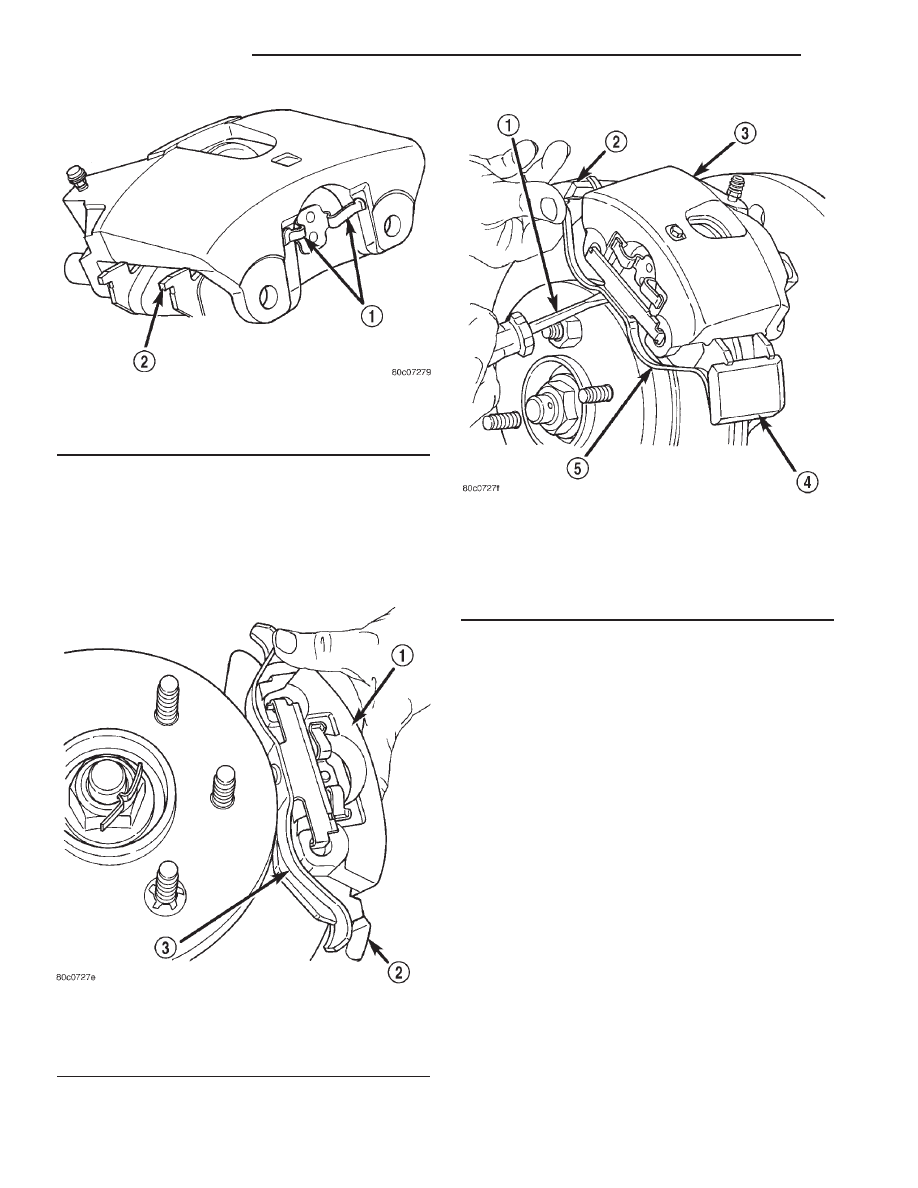
the spring (Fig. 13) and hold the end under the
adapter. With a screw driver pry up on the spring
(Fig. 14) to seat the spring into the other caliper
hole.

NOTE: Verify the spring is seated properly into the
caliper holes.

(9) Install wheel and tire assembly. (Refer to 22 -

TIRES/WHEELS/WHEELS - STANDARD PROCE-
DURE).

(10) Remove support and lower vehicle.
(11) Pump brake pedal to seat brake shoes.
(12) Fill brake fluid reservoir.
(13) Verify a firm brake pedal before moving vehi-

cle.

COMBINATION VALVE

DESCRIPTION

The combination valve contains a pressure differ-

ential valve and switch and a rear brake proportion-
ing valve. The valve is not repairable and must be
replaced as an assembly if diagnosis indicates this is
necessary.

OPERATION

PRESSURE DIFFERENTIAL VALVE

The pressure differential switch is connected to the

brake warning light. The switch is actuated by move-
ment of the switch valve. The switch monitors fluid
pressure in the separate front/rear brake hydraulic
circuits.

Fig. 12 Outboard Shoe Retainer Spring

1 - SEAT RETAINER SPRING ENDS IN CALIPER
2 - OUTBOARD SHOE

Fig. 13 Caliper Spring

1 - CALIPER
2 - ADAPTER
3 - CALIPER SPRING

Fig. 14 Seat Caliper Spring

1 - SCREWDRIVER
2 - ADAPTER
3 - CALIPER
4 - ADAPTER
5 - CALIPER SPRING

5 - 12

BRAKES - BASE

AN

BRAKE PADS/SHOES (Continued)

A decrease or loss of fluid pressure in either

hydraulic circuit will cause the switch valve to shut-
tle to the low pressure side. Movement of the valve
pushes the switch plunger upward. This action closes
the switch internal contacts completing the electrical
circuit to the red warning light. The switch valve will
remain in an actuated position until repairs to the
brake system are made.

PROPORTIONING VALVE

The proportioning valve is used to balance front-

rear brake action at high decelerations. The valve
allows normal fluid flow during moderate braking.
The valve only controls fluid flow during high decel-
erations brake stops.

DIAGNOSIS AND TESTING - COMBINATION
VALVE

Pressure Differential Switch

(1) Have helper sit in drivers seat to apply brake

pedal and observe red brake warning light.

(2) Raise vehicle on hoist.
(3) Connect bleed hose to a rear wheel cylinder

and immerse hose end in container partially filled
with brake fluid.

(4) Have helper press and hold brake pedal to floor

and observe warning light.

(a) If warning light illuminates, switch is operat-

ing correctly.

(b) If light fails to illuminate, check circuit fuse,

bulb, and wiring. The parking brake switch can be
used to aid in identifying whether or not the brake
light bulb and fuse is functional. Repair or replace
parts as necessary and test differential pressure
switch operation again.
(5) If warning light still does not illuminate,

switch is faulty. Replace combination valve assembly,
bleed brake system and verify proper switch and
valve operation.

REMOVAL

(1) Disconnect wire from the pressure differential

switch.

(2) Disconnect rear brake lines from combination

valve.

(3) Remove the bolt from the combination valve

and remove the valve.

INSTALLATION

(1) Install the combination valve to the bracket

and tighten the mounting bolt to 20-27 N·m (15-20 ft.
lbs.). If vehicle is equipped with ABS brakes tighten
the bolt to 10-13 N·m (7-10 ft. lbs.).

(2) Install the brake lines to the combination

valve.

(3) Tighten the brake line to 19 N·m (170 in. lbs.).
(4) Connect the wire to the pressure differential

switch.

(5) Bleed brakes system. (Refer to 5 - BRAKES -

STANDARD PROCEDURE).

DISC BRAKE CALIPERS

DESCRIPTION

The calipers are a single piston type. The calipers

are free to slide laterally, this allows continuous com-
pensation for lining wear.

OPERATION

When the brakes are applied fluid pressure is

exerted against the caliper piston. The fluid pressure
is exerted equally and in all directions. This means
pressure exerted against the caliper piston and
within the caliper bore will be equal (Fig. 15).

Fluid pressure applied to the piston is transmitted

directly to the inboard brake shoe. This forces the
shoe lining against the inner surface of the disc
brake rotor. At the same time, fluid pressure within
the piston bore forces the caliper to slide inward on
the mounting bolts. This action brings the outboard

Fig. 15 Brake Caliper Operation

1 - CALIPER
2 - PISTON
3 - PISTON BORE
4 - SEAL
5 - INBOARD SHOE
6 - OUTBOARD SHOE

AN

BRAKES - BASE

5 - 13

COMBINATION VALVE (Continued)

brake shoe lining into contact with the outer surface
of the disc brake rotor.

In summary, fluid pressure acting simultaneously

on both piston and caliper, produces a strong clamp-
ing action. When sufficient force is applied, friction
will attempt to stop the rotors from turning and
bring the vehicle to a stop.

Application and release of the brake pedal gener-

ates only a very slight movement of the caliper and
piston. Upon release of the pedal, the caliper and pis-
ton return to a rest position. The brake shoes do not
retract an appreciable distance from the rotor. In
fact, clearance is usually at, or close to zero. The rea-
sons for this are to keep road debris from getting
between the rotor and lining and in wiping the rotor
surface clear each revolution.

The caliper piston seal controls the amount of pis-

ton extension needed to compensate for normal lining
wear.

During brake application, the seal is deflected out-

ward by fluid pressure and piston movement (Fig.
16). When the brakes (and fluid pressure) are
released, the seal relaxes and retracts the piston.

The amount of piston retraction is determined by

the amount of seal deflection. Generally the amount
is just enough to maintain contact between the pis-
ton and inboard brake shoe.

REMOVAL

(1) Clean master cylinder reservoir and filler caps.
(2) Remove reservoir filler cap and drain approxi-

mately 1/4 of fluid from reservoir. Use clean suction
gun or similar device to drain fluid.

(3) Raise and support vehicle.
(4) Remove front wheel and tire assemblies.

(5) Bottom caliper pistons in bores with large

C-clamp. Position clamp frame on rear of caliper and
clamp screw on outboard brake shoe.

(6) Disconnect brake hose at caliper. Discard hose

fitting washers if worn, or damaged (Fig. 17).

(7) With a screw driver pry up on the caliper

spring and pull the spring out of the caliper holes.

(8) Remove caliper and brake shoes from caliper.

DISASSEMBLY

(1) Drain old brake fluid out of caliper into drain

pan.

(2) Remove piston dust boot (Fig. 18). Use screw-

driver to push boot out of groove.

(3) Pad outboard shoe side of caliper interior with

a minimum 1 inch thickness of shop towels (Fig. 19).
Towels will prevent piston damage when piston
comes out of the caliper bore.

(4) Remove caliper piston with short bursts of com-

pressed air. Apply air pressure through fluid inlet
port of caliper (Fig. 19).

CAUTION: Do not blow the piston out of the bore
with sustained air pressure. This could result in a
cracked piston. Use only enough air pressure to
ease the piston out.

WARNING: NEVER ATTEMPT TO CATCH THE PIS-
TON AS IT LEAVES THE BORE. THIS MAY RESULT
IN PERSONAL INJURY.

(5) Remove caliper piston seal with wood pencil or

plastic tool (Fig. 20). Do not use metal tools as they
will scratch piston bore.

(6) Remove caliper slide pin bushings and boots.

Fig. 16 Lining Wear Compensation By Piston Seal

1 - PISTON
2 - CYLINDER BORE
3 - PISTON SEAL BRAKE PRESSURE OFF
4 - CALIPER HOUSING
5 - DUST BOOT
6 - PISTON SEAL BRAKE PRESSURE ON

Fig. 17 Caliper Brake Hose Connection

1 - CALIPER
2 - FRONT BRAKE HOSE
3 - FITTING WASHERS

5 - 14

BRAKES - BASE

AN

DISC BRAKE CALIPERS (Continued)

(7) Remove caliper bleed screw and cap.

CLEANING

Clean the caliper components with clean brake

fluid or brake clean only. Wipe the caliper and piston
dry with lint free towels or use low pressure com-
pressed air.

CAUTION: Do not use gasoline, kerosene, paint
thinner, or similar solvents. These products may
leave a residue that could damage the piston and
seal.

INSPECTION

The piston is made from a phenolic resin (plastic

material) and should be smooth and clean.

The piston must be replaced if cracked or scored.

Do not attempt to restore a scored piston surface by
sanding or polishing.

CAUTION: If the caliper piston is replaced, install
the same type of piston in the caliper. Never inter-
change phenolic resin and steel caliper pistons.
The pistons, seals, seal grooves, caliper bore and
piston tolerances are different.

The bore can be lightly polished with a brake

hone to remove very minor surface imperfections
(Fig. 21). The caliper should be replaced if the bore is
severely corroded, rusted, scored, or if polishing
would increase bore diameter more than 0.025 mm
(0.001 inch).

INSTALLATION

(1) Install brake shoes in caliper. (Refer to 5 -

BRAKES/HYDRAULIC/MECHANICAL/BRAKE
PADS/SHOES - INSTALLATION).

Fig. 18 Piston Dust Boot

1 - PISTON BOOT DUST

Fig. 19 Caliper Piston

1 - AIR GUN NOZZLE
2 - FLUID INLET PORT
3 - CALIPER PISTON
4 - PADDING MATERIAL (TO PROTECT PISTON)

Fig. 20 Caliper Piston Seal

1 - PISTON SEAL
2 - WOOD PENCIL

AN

BRAKES - BASE

5 - 15

DISC BRAKE CALIPERS (Continued)


Content   ..  232  233  234  235   ..