Dodge Dakota (R1). Manual - part 3
system will stop pulsing the lights and return to the
“armed” state. The cause of the last 4 alarm triggers
is stored by the CTM and may be retrieved by the
DRBIII
t. The system may be disarmed by either an
unlock command from a valid RKE key fob by using
a key in either door, or by using a valid SKIM key in
the ignition. The door key cylinders are equipped
with disarm switches. There is also a VTSS lamp on
the dash that provides information to the driver
about the state of the vehicle theft system.
3.14
WINDSHIELD WIPER SYSTEM
The R1 truck equipped with a highline CTM will
utilize speed sensitive intermittent wipers. A base
CTM will provide for intermittent wipers without
the speed sensitive feature. The low and high
speeds are controlled through the wiper stalk
switch. The intermittent portion of the wiper con-
trol is handled by the CTM through the intermit-
tent wiper relay. When the module detects a de-
crease in delay time as selected by the driver, an
immediate wipe of the windshield takes place and
the new delay interval is implemented.
3.15
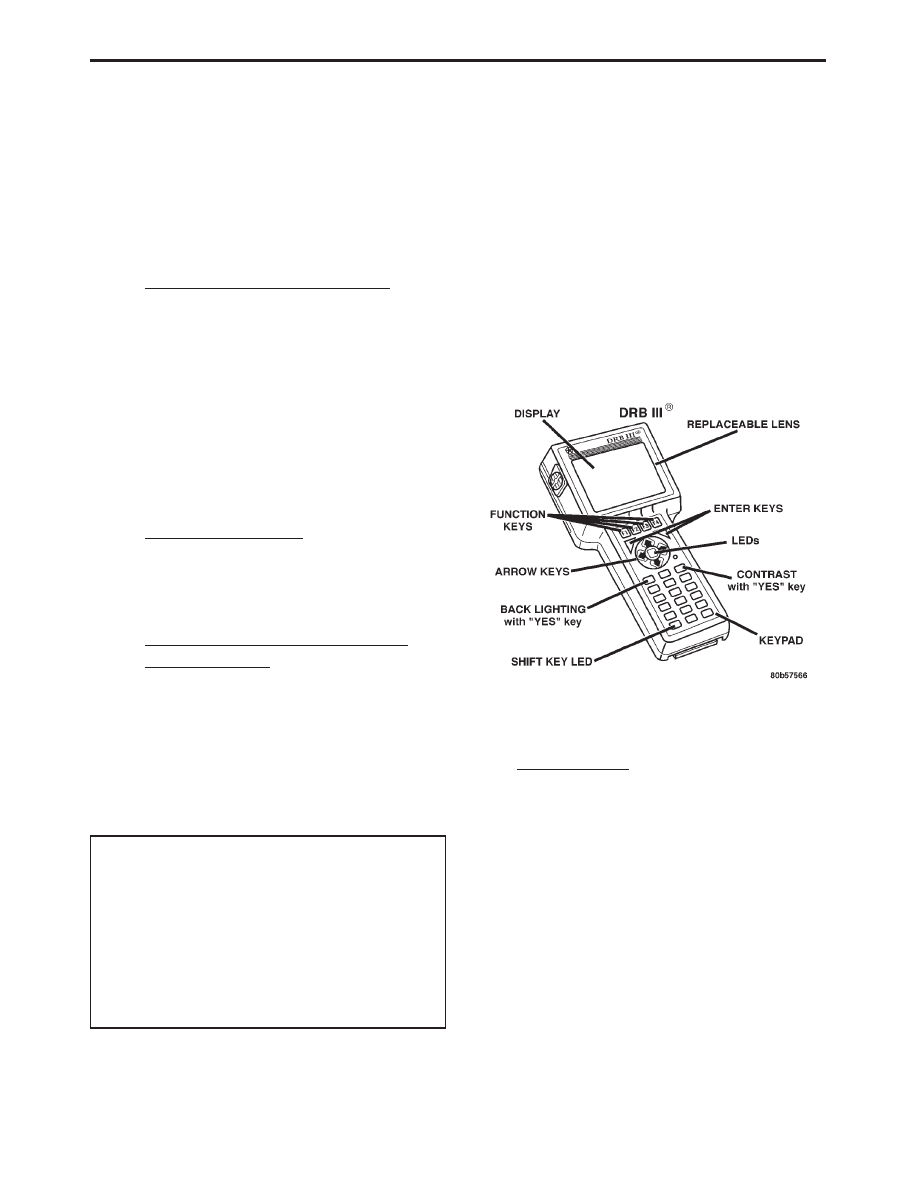
USING THE DRBIII
T
Refer to the DRBIII
t user’s guide for instructions
and assistance with reading trouble codes, erasing
trouble codes and other DRBIII
t functions.
3.16
DRBIII
T ERROR MESSAGES AND
BLANK SCREEN
Under normal operation, the DRBIII
t will dis-
play one of only two error messages:
– User-Requested
WARM
Boot
or
User
Requested COLD Boot
If the DRBIII
t should display any other error
message, record the entire display and call the Star
Center for information and assistance. This is a
sample of such an error message display:
ver: 2.14
date: 26 Jul93
file: key itf.cc
date: Jul 26 1993
line: 548
err. Ox1
User-Requested COLD Boot
Press MORE to switch between this display
and the application screen.
Press F4 when done noting information.
3.16.1
DRBIII
T DOES NOT POWER UP
(BLANK SCREEN)
If the LED’s do not light or no sound is emitted at
start up, check for loose cable connections or a bad
cable. Check the vehicle battery voltage (data link
connector cavity 16). A minimum of 11 volts is
required to adequately power the DRBIII
t. Also,
check for proper grounds at DLC cavities 4 and 5.
If all connections are proper between the
DRBIII
t and the vehicle or other devices, and the
vehicle battery is fully charged, an inoperative
DRBIII
t may be the result of a faulty cable or
vehicle wiring.
3.16.2
DISPLAY IS NOT VISIBLE
Low temperatures will affect the visibility of the dis-
play. Adjust the contrast to compensate for this condition.
4.0
DISCLAIMERS, SAFETY,
WARNINGS
4.1
DISCLAIMERS
All information, illustrations, and specifications
contained in this manual are based on the latest
information available at the time of publication.
The right is reserved to make changes at any time
without notice.
9
GENERAL INFORMATION