Content .. 1114 1115 1116 1117 ..
Dodge Dakota (ND). Manual - part 1116
C140B- TRANSFER CASE MOTOR CONTROL CIRCUIT LOW (CONTINUED)
12.
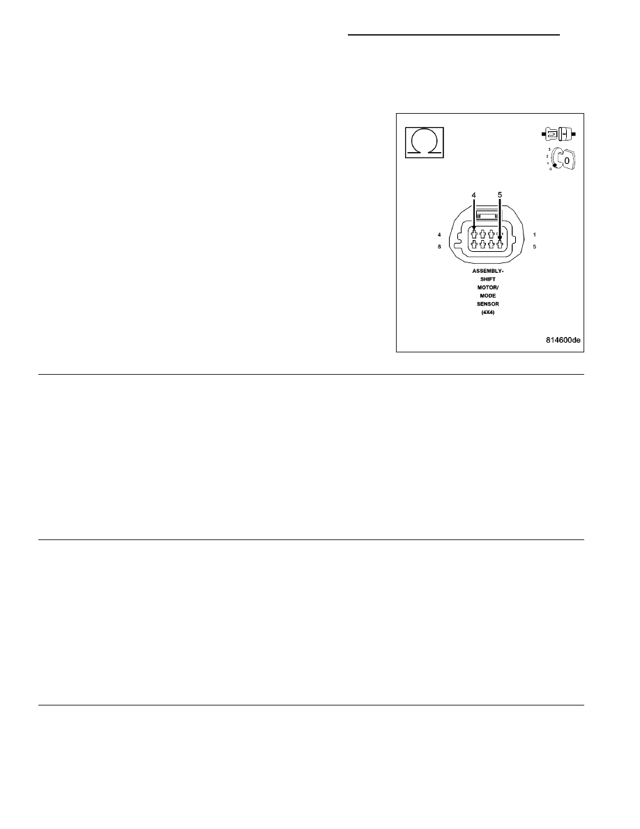
(T315) SHIFT MOTOR CONTROL A CIRCUIT SHORTED TO (T316) SHIFT MOTOR CONTROL B CIRCUIT
(IPM)
Disconnect the Integrated Power Module C5 harness connector.
Measure the resistance between (T315) Shift Motor Control A circuit
and the (T316) Shift Motor Control B circuit at the Shift Motor/Mode
Sensor Assembly harness connector.
Is the resistance below 5.0 ohms?
Yes
>> Repair the (T315) Shift Motor Control A circuit for a short
to the (T316) Shift Motor Control B circuit.
Perform the TRANSFER CASE VERIFICATION TEST-
VER 1. (Refer to 8 - ELECTRICAL/ELECTRONIC CON-
TROL MODULES/TRANSFER CASE CONTROL MODULE
- DIAGNOSIS AND TESTING)
No
>> Go to 14
13.
SHIFT MOTOR/MODE SENSOR ASSEMBLY
Using the wiring diagram/schematic as a guide, inspect all wiring and connectors that pertain to this circuit.
Were any problems found?
Yes
>> Repair as necessary.
Perform the TRANSFER CASE VERIFICATION TEST-VER 1. (Refer to 8 - ELECTRICAL/ELECTRONIC
CONTROL MODULES/TRANSFER CASE CONTROL MODULE - DIAGNOSIS AND TESTING)
No
>> Replace the Shift Motor/Mode Sensor assembly in accordance with the Service Information.
Perform the TRANSFER CASE VERIFICATION TEST-VER 1. (Refer to 8 - ELECTRICAL/ELECTRONIC
CONTROL MODULES/TRANSFER CASE CONTROL MODULE - DIAGNOSIS AND TESTING)
14.
INTEGRATED POWER MODULE
Using the wiring diagram/schematic as a guide, inspect all wiring and connectors that pertain to this circuit.
Were any problems found?
Yes
>> Repair as necessary.
Perform the TRANSFER CASE VERIFICATION TEST-VER 1. (Refer to 8 - ELECTRICAL/ELECTRONIC
CONTROL MODULES/TRANSFER CASE CONTROL MODULE - DIAGNOSIS AND TESTING)
No
>> Replace the Integrated Power Module in accordance with the Service Information.
Perform the TRANSFER CASE VERIFICATION TEST-VER 1. (Refer to 8 - ELECTRICAL/ELECTRONIC
CONTROL MODULES/TRANSFER CASE CONTROL MODULE - DIAGNOSIS AND TESTING)
21 - 856
TRANSFER CASE - ELECTRICAL DIAGNOSTICS
ND