Daewoo Musso. Manual - part 311


  Index      Daewoo     Daewoo Musso - service repair manual


Search            


Content   ..  309  310  311  312   ..


Daewoo Musso. Manual - part 311


5D2-46  TRANSFER CASE (TOD)

23. Remove the internal snap ring from the planetary carrier

and separate the front planet from the input shaft.

24. Remove the external snap ring from the input shaft. Place

the input shaft in a vise and remove the bearing. Remove
the thrust washer, thrust plate and the sun gear off the
input shaft.

25. Inspect the bushing and needle bearing in the end of the

input shaft for wear or damage.

Notice

Under normal use, the needle bearing and bushing should
not require replacement. If replacement is required, the
bushing and needle bearing must be replaced as a set.

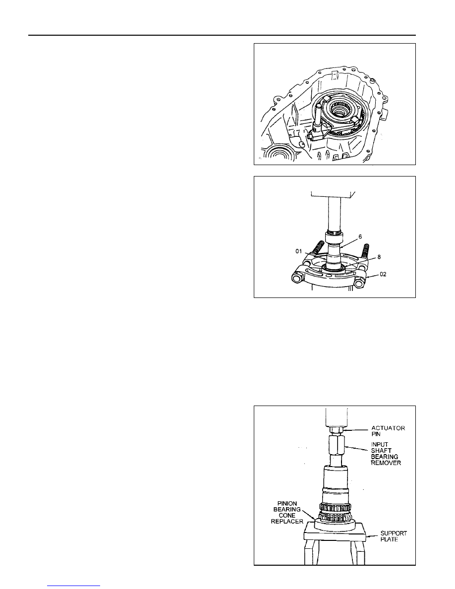
26. If replacement of the needle bearing and bushing is

required, press the bearing and bushing is required, press
the bearing and bushing out as follows:

a. Position the input shaft on Axle Bearing/Seal plate,and

using Pinion Bearing Cone Replacer as a spacer.

b. Insert Input Shaft Bearing Remover into the input shaft

so it is resting on top of the bearing cage.

c. Tighten the actuator pin until it stops, then press the

bearing and bushing out together.

6

Input Shaft

8

Bearig

01

Pinion Bearing Cone Remover

02

Compress the Dowel

27. If required, remove the front yoke to flange seal by prying

and pulling on the curved-up lip of the yoke to flange seal.
Do not damage the bearing, bearing cage or case.

28. If required, remove the internal snap ring retaining the

front output shaft ball bearing and remove the bearing.

TRANSFER CASE (TOD)  5D2-47

Assembly Procedure

Assembly

Before assembly, lubricate all parts with Automatic Transmission
Fluid or equivalent.

1. If removed, drive the bearing into the front output case bore.

Drive the bearing in staight, making sure it is not cocked in
the bore. Install the internal snap ring that retains the bearing
to the front case.

2. If removed, install the front yoke to flange seal in the front

case bore.

3. If removed, install the yoke to flange seal into the mounting

adapter bore.

4

Sun Gear

5

Thrust Plate

6

Input Shaft

7

Thrust Washer

8

Bearing

9

External Snap Ring

10

Internal Snap Ring

4. If the input shaft needle bearing and bushing were removed,

install a new bearing and bushing as detailed in the following
steps:

Press a new needle bearing, then a new bushing in the
input shaft as follows:

a. Position the input shaft on Axle Bearing/Seal Plate or

equivalent, and Pinion  Bearing Cone Replacer as a
spacer.

b. Press a new needle bearing into the end of the input

shaft until it seats in the input shaft.

c. Press in a new bushing.

5. The recessed face of the sun gear and the snap ring groove

on the bearing outer race should be toward the rear of the
transfer case. The stepped face of the thrust washer should
face toward the bearing.

Slide the sun gear, thrust plate and thrust washer into
position on the input shaft. Press the bearing over the input
shaft. Install the external snap ring to the input shaft.

5D2-48  TRANSFER CASE (TOD)

  6. Install the front planet to the sun gear and input shaft.

Install the internal snap ring to the planetary carrier.

  7. Place the tanged snap ring in the case. Expand snap ring

with snap ring pliers and install planetary carrier assembly.
Check installation by holding the case and carefully tapping
the face of the input shaft against a wooden block to make
sure the snap ring is installed.

  8. Remove all traces of gasket sealant from the front case

and mounting adapter mating surfaces. Install a bead of
gasket sealant on the surface of the front case.

  9. Install the high-low shift fork and high-low collar as an

assembly into the front planet.

Notice

Make sure that the nylon wear pads are installed on the
shift fork and snapped securely into place.

12

Rear Output Shaft

13

Oil Strainer

14

Coupling Hose

15

Hose Clamp

16

Pump Body

10. If new pump is used, align the flat of the output shaft and

the flat of the pump. Slide the pump onto the output shaft.

l

Do not disassemble oil pump. It is serviced only as an

assembly. Check the pump to make sure the pump
rotates freely.

l

Do not remove the plastic insert from the bore of the

new pump. Discard it after it slides out during pump
installation to the rear output shaft.

l

While turning the output shaft, prime the pump through

the oil filter pickup tube or housing inlet hole with clean
Automatic Transmission Fluid or equivalent.

11. Inspect the outside surfaces and bore of the oil pump. If

there is no discoloration in the pump housing, gear or cover,
and the pump bore and the lube holes of the output shaft
show evidence of oil, the pump is working.

TRANSFER CASE (TOD)  5D2-49

12. Install the output shaft and oil pump in the input shaft.

Make sure that the internal splines of the ouput shaft
engage the internal splines of the high-low shift collar. Make
sure that the oil pump retainer arm and oil filter leg are in
the groove and slot of the front case.

13. Install the magnet in the slot in the front case just above

the oil filter leg.

14. Install the front output shaft in the front case.

15. Install the thrust washer on the rear output shaft. Install

the chain, drive sprocket and driven sprocket as an
assembly over the output shaft.

Notice

l

The driven sprocket (on the front output shaft) must

be installed with the marking REAR facing toward the
rear case, if so marked.

l

Drive sprocket has a bushing pressed into it.

16. Install tone wheel onto the front output shaft. Make sure

the spline on the tone wheel engages the spline on the
front output shaft.

17. Install clutch pack assembly onto the rear output shaft.

Make sure the spline of the clutch pack engages to the
spline of the sprocket.

18. Install snap ring onto the rear output shaft. Start the snap

ring over the spline and use the wave spring to seat the
snap ring in the snap ring groove. If the snap ring will not
install, the thrust washer inside the clutch pack may not
be seated properly.

12

Rear Output Shaft

16

Oil Pump

61

Magnet

12

Rear Output Shaft

13

Oil Strainer

16

Oil Pump

16a Pump Retainer


Content   ..  309  310  311  312   ..