Daewoo Musso. Manual - part 289


  Index      Daewoo     Daewoo Musso - service repair manual


Search            


Content   ..  287  288  289  290   ..


Daewoo Musso. Manual - part 289


5C-12  CLUTCH

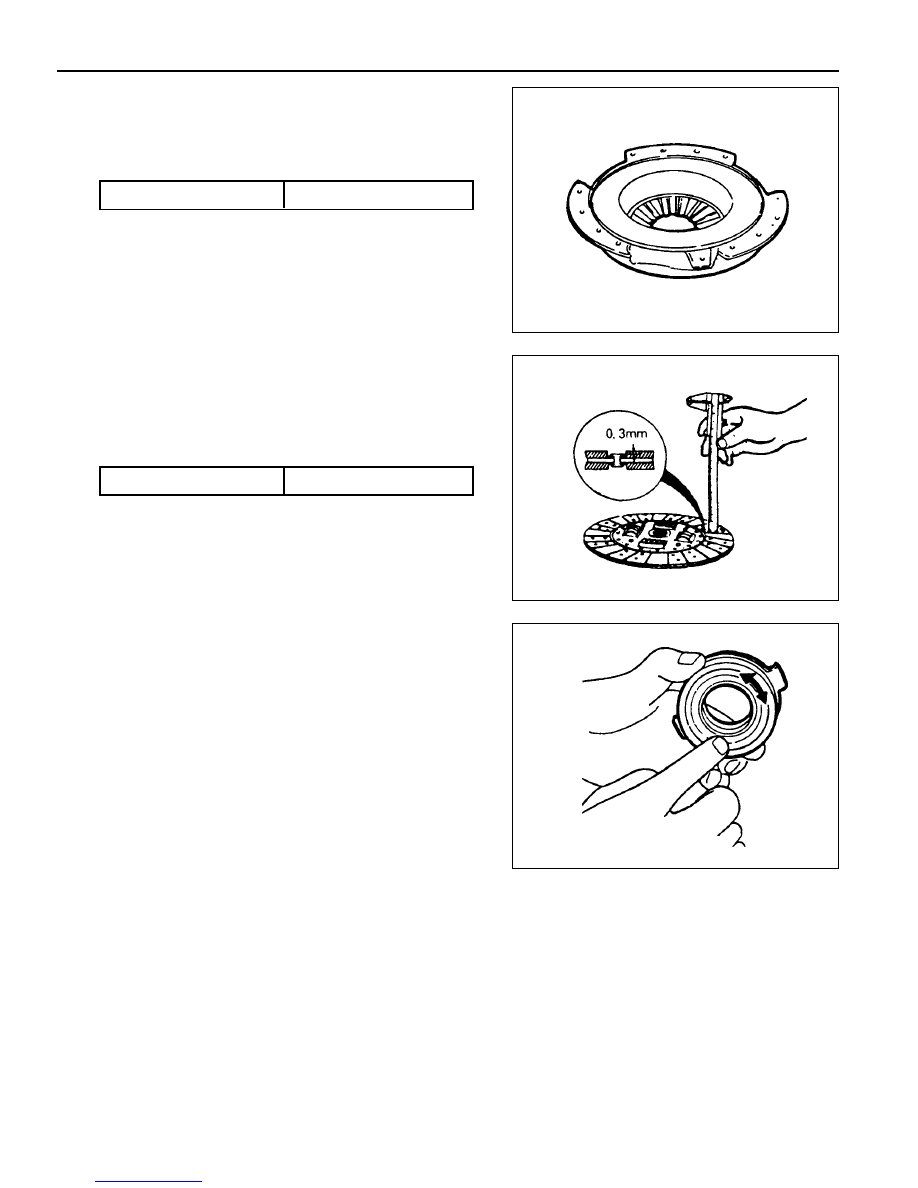
Inspection Procedure

1. Clutch Cover

l

Check the diaphragm spring tip for wear and height

unevenness.

l

Check the pressure plate surface for wear, crack and

discoloration.

l

Check the strap plate rivet for looseness and replace

the clutch cover if loosened.

Unevenness Limit

0.8 mm

2. Clutch Disc

l

Check the facing for rivet looseness, excessive runout,

sticks, oil and grease.

l

Measure the rivet head depth.

If out limit, replace the disc.

3. Clutch Release Bearing

l

The release bearing is permanently lubricated and

requires no cleaning.

l

Check the bearing for sticks, damage, abnormal noise,

turning drag and wear.

4. Release Fork

l

If there is abnormal wear in contact point with bearing,

replace the release fork.

Wear Limit

0.3 mm

CLUTCH  5C-13

MASTER CYLINDER

1 Snap Pin
2 Clevis Pin
3 Clevis
4 Lock Nut
5 Flange Nut ........................................... 30-40 Nm
6 Push Rod
7 Cylinder Body
8 Oil Pipe ................................................ 15-18 Nm

9 Clamp

10 Reservoir

11 Spring

12 Piston Assembly
13 Boot
14 Plate
15 Snap Ring

Notice

Do not disassemble the No.12.

5C-14  CLUTCH

Removal & Installation Procedure

1. Draw out the fluid.

2. Pull out the snap pin and clevis pin from the clutch pedal

connection.

3. Remove the clutch tube.

Installation Notice

Tightening  Torque

15 - 18 Nm

Notice

Be careful not the fluid contact a painted surface.

4. Remove the master cylinder mounting nuts and pull off the

master cylinder.

Installation Notice

Tightening  Torque

8 - 18 Nm

5. Check the clutch pedal operation.

6. Bleed the clutch system.

CLUTCH  5C-15

CLUTCH PEDAL

1 Snap Pin ................................................ Replace
2 Clevis Pin ...................................... Apply Grease
3 Master Cylinder Push Rod
4 Gasket
5 Nut ....................................................... 16-22 Nm
6 Spring washer
7 Bolt ........................................................ 8-18 Nm
8 Fulcrum Pin

9 Turn Over Spring .......................... Apply Grease

10 Bushing ......................... Replace, Apply Grease

11 Full Stroke Stopper Contact Pad

12 Clutch Pedal
13 Pedal Pad
14 Pedal Mounting Bracket
15 Stopper Bolt .......................................... 21-25Nm
16 Clutch Interlock Switch

Notice

Assembly should follow the disassembly procedure in the reverse order.

Grease specification : Long - term grease (T/Mn DBL6611.00)


Content   ..  287  288  289  290   ..