Daewoo Musso. Manual - part 191


  Index      Daewoo     Daewoo Musso - service repair manual


Search            


Content   ..  189  190  191  192   ..


Daewoo Musso. Manual - part 191


1F3-44  OM600 ENGINE CONTROLS

Tools Required

617 589 09 21 00  Rl Sensor

617 589 10 21 00  Timing Tester

667 589 00 21 00  TDC Pulse Generator

Commercial Tools

Item

   Digital Tester

With Pulse Generator

Without Pulse Generator

Tools

Bosch, MOT 001.03

Hartmann & Braun, EOMT3

Bosch, ETD 019.00

Sun, DIT 9000

ALV, Diesel - Tester 875

Digital tester (RIV Method)

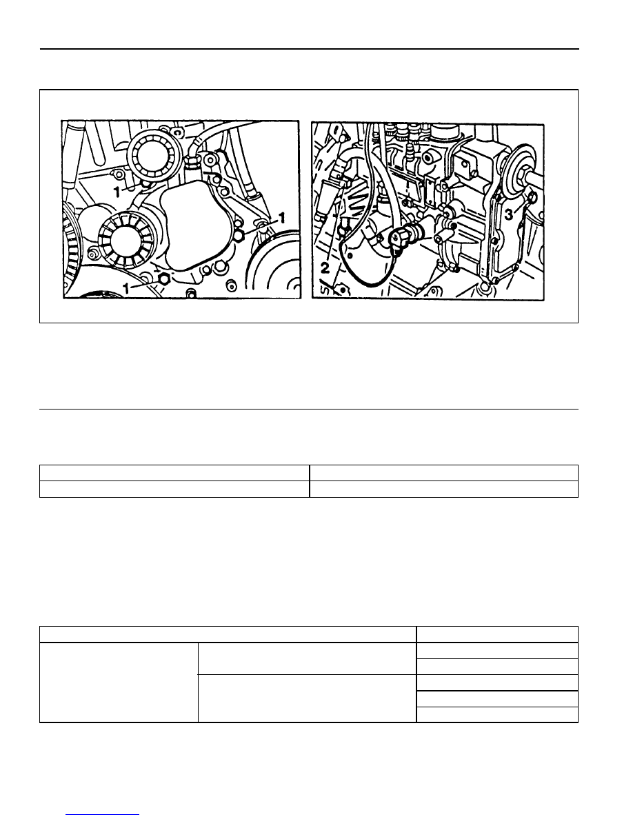
1 Bolt ............................................................ 23Nm
2 Adjusting

Screw ....... To the right : start of delivery retarded

To the left : start of delivery advanced

3 Bolt ............................................................ 23Nm

Service Data

Start of Delivery (RIV)

Ldling Speed

ATDC 14° - 16°

OM661LA : 720 - 820 rpm, OM662LA : 750 - 850 rpm

OM600 ENGINE CONTROLS  1F3-45

Adjustment Procedure

1. Remove the bolt (3) at the supporting bracket.

2. remove the bolts (1) at the timing case cover.

3. Run the engine at idle speed.

4. Turn the adjusting screw (2) until the specification (15° ± 1°

ATDC) is indicated on the digital tester.

To the Right

To the Left

Start of Delivery Retarded

Start of Delivery Advanced

1F3-46  OM600 ENGINE CONTROLS

Tools Required

000 589 77 03 00  Box Wrench Insert

601 589 00 08 00  Flange

601 589 05 21 00  Locking Screw

601 589 05 14 00  Assembly CageRemoval

FUEL INJECTION PUMP

Preceding Work : Removal of vacuum pump

Removal of air cleaner housing
Removal of intake manifold

18 Chain Tensioner......................................... 80Nm
19 Seal ....................................................... Replace
20 Bolt(Left-Hand Thread) .............................. 46Nm
21 Washer
22 Bolt ............................................................ 23Nm
23 Seal ....................................................... Replace

24 Oil Pan
25 Fuel Injection Pump
26 Seal ....................................................... Replace
27 Screw Plug ................................................. 30Nm
28 Square Nut

OM600 ENGINE CONTROLS  1F3-47

2. Remove the connecting rod (9).

3. Disconnect the vacuum lines (13, 14).

4. Remove the accelerator control damper (10).

(Manual transmission vehicle)

5. Remove the suction line (16) and pressure line (4).

6. Remove the banjo bolt (1) and then remove the seal (2)

and fuel line (3).

7. Remove the plastic clip (8) on the injection line.

Removal Procedure

1. Position then no.1 cylinder at 15° ATDC.

Notice

Do not rotate the engine in opposition direction of engine
rotation.

8. Disconnect the injection lines (15) from the injection pump

(25).

9. Remove the banjo bolt (1) and then remove the seal (7)

and return line (5).


Content   ..  189  190  191  192   ..