Daewoo Musso. Manual - part 190


  Index      Daewoo     Daewoo Musso - service repair manual


Search            


Content   ..  188  189  190  191   ..


Daewoo Musso. Manual - part 190


1F3-40  OM600 ENGINE CONTROLS

Start of Delivery (RIV)

Idle Speed

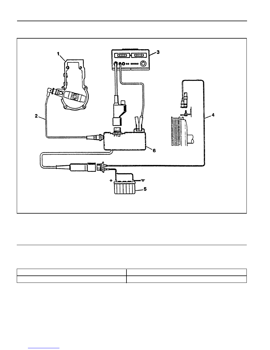
(Connection Diagram for Testers With Adapter)

1 Fuel Injection Pump
2 Rl Sensor
3 Digital Tester

4 TDC Pulse Sender Unit
5 Battery
6 Rl Pulse Generator

Service Data

ATDC 14° - 16°

OM661LA : 720 - 820 rpm, OM662LA : 750 - 850 rpm

OM600 ENGINE CONTROLS  1F3-41

With Pulse Generator

Tools Required

617 589 09 21 00  Rl Sensor

617 589 10 21 00  Timing Tester

667 589 00 21 00  TDC Pulse Generator

Commercial Tools

Item

Digital Tester

Without Pulse Generator

Tools

Bosch, MOT 001.03

Hartmann & Braun, EOMT3

Bosch, ETD 019.00

Sun, DIT 9000

ALV, Diesel - Tester 875

Test Procedure

1. Remove the screw plug (7) and seal (8) collect oil in a suitable

vessel.

2. Install the Rl sensor into the governor housing of injection

pump (1).

Rl Sensor 617 589 10 21 00

3. Connect the digital tester and TDC pulse sender unit

according to connection diagram.

4. Run the engine at idle speed and check the Rl value on the

digital tester

Notice

If out of standard, adjust the start of delivery.

5. Stop the engine.

6. Remove the Rl sensor, digital tester and TDC pulse sender

unit.

7. Replace the seal and tighten the plug.

8. Check engine oil level and adjust if necessary.

Rl value

ATDC 14° - 16°

Tightening Torque

30 Nm

1F3-42  OM600 ENGINE CONTROLS

After Testing

Preceding Work : Start of delivery test

Position Sensor (RIV method)

1 Adjusting Screw
2 Bolt ............................................................ 23Nm
3 Fuel Injection Pump

4 Bolt ............................................................ 23Nm
5 Scale .......... Rl start of delivery = 14° - 16° ATDC

OM600 ENGINE CONTROLS  1F3-43

Tools Required

617 589 08 21 00  Position Sensor

Adjustment Procedure

1. Position the No. 1 cylinder at ATDC 15°

Notice

Do not rotate the engine in opposite direction of engine
rotation.

2. Remove the bolt (2) at the supporting bracket.

3. Remove the bolt (4).

4. Turn the adjusting screw (1) until both lamps ‘A’ + ‘B’ on

the position sensor light up.

Notice

If the adjustment range is not adequate, remove the injection
pump and reinstall.

Position Sensor 617 589 08 21 00

5. After adjusting, retighten all the bolt to the specified torque.

To the right

To the left

Start of delivery retarded

Start of delivery advanced


Content   ..  188  189  190  191   ..