Daewoo Musso. Manual - part 140
OM600 ENGINE ELECTRICAL 1E3-7
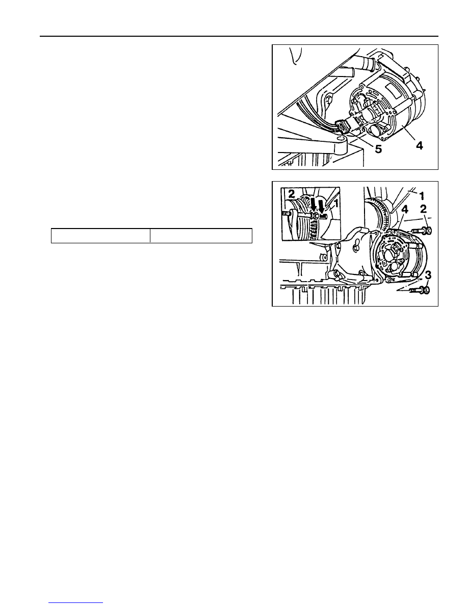
Removal & Installation Procedure
1. Disconnect the negative terminal of the battery.
2. Disconnect the plug connection (5).
3. OM 662 Engine
Align the groove of cooling fan with bolt (2) (arrow).
4. Remove the bolts (2, 3) and take out the alternator.
5. Installation should follow the removal procedure in the
reverse order.
Tightening Torque
45 Nm