Daewoo Musso. Manual - part 38


  Index      Daewoo     Daewoo Musso - service repair manual


Search            


Content   ..  36  37  38  39   ..


Daewoo Musso. Manual - part 38


1B1-88  M162 ENGINE MECHANICAL
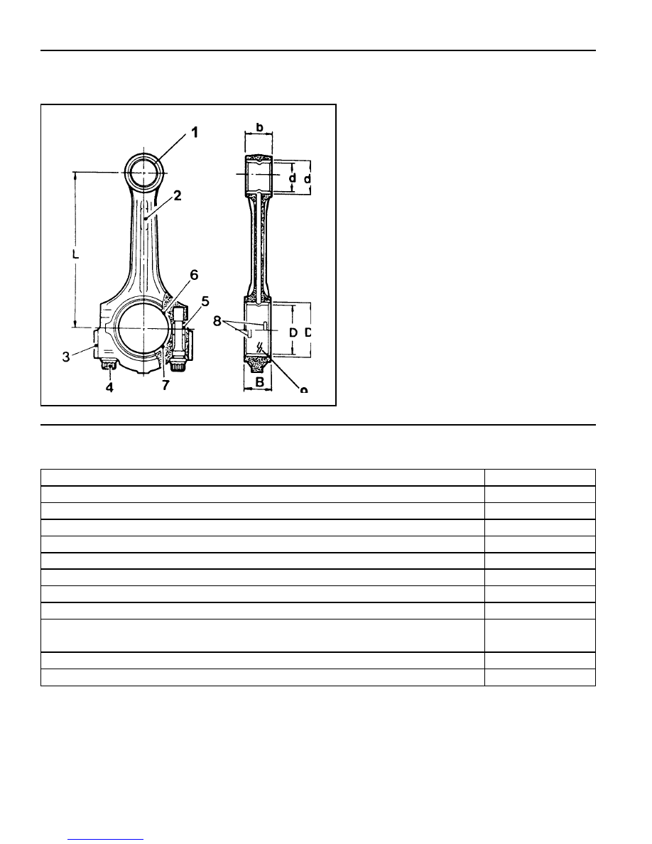
CONNECTING ROD

Preceding Work : Removal of piston

1 Connecting Rod Bushing
2 Oil Gallery
3 Balance Weight
4 Connecting Rod Bolt

(M9 x 52, 12 m pieces) .. 1st step 40+5 Nm

2nd step 90°+10°

5 Fit Sleeve
6 Upper Connecting Rod Bearing
7 Lower Connecting Rod Bearing
8 BearingShell Lug
9 Marking [Indication(//) or Numbers]

Service Data Standard

Distance (L) from The Connecting Rod Bearing Bore Center to The Bushing Bore Center

Width of The Connecting Rod (B) at Bearing Bore

Width of The Connecting Rod (b) at Bushing Bore

Basic Bore at The Bearing Shell (D1)

Basic Bore at The Bushing (d1)

Bushing Inner Diameter (d)

Clearance Between The Piston Pin and The Bushing

Peak-to-valley Height of Connecting Rod Bushing on Inside

Permissible Wwist of Connecting Rod Bearing Bore to Connecting Rod Bushing Bore

Permissible Deviation of Axial Paralleism of Connecting Rod Bearing Bore to Connecting

Rod Bushing Core

Permissible Deviation of Connecting Rod Bearing Bore from Concentricity

Permissible Difference of Each Connecting Rod in Weight

145 ± 0.05 mm

21.940 - 22.000 mm

21.940 - 22.000 mm

51.600 - 51.614 mm

24.500 - 24.571 mm

22.007 - 22.013 mm

0.007 - 0.018 mm

0.005 mm

0.15 mm

0.07 mm

0.01 mm

0.4 g

M162 ENGINE MECHANICAL  1B1-89

Inspection

1. Measure the basic bore of the connecting rod bearing.

Notice

If the basic bore exceeds the value of 51.614mm, replace
the bearing or check the connecting rod.

2. Check connecting rod bolts.

3. Check the assembly mark(indication//or number:arrow) of

the connecting rods and the bearing cap when installing.

Notice

l

Make sure it doesn’t exceed over 4g with other
connecting rods when replacing the connecting rods.

l

Check if the connecting rod and the bearing cap are
accurately seated on the groove when replacing the
bearing.

Notice

If the length exceeds max. length, replace it.

Length When New (L)

Max. Length (L)

Tightening Torque

51.7 - 52 mm

52.9 mm

1st step 40 + 5 Nm

2nd step 90°+10°

1B1-90  M162 ENGINE MECHANICAL

PISTON RING

Preceding Work : Removal of piston

1 Piston Compression Ring
2 Piston Compression Ring
3 Piston Oil Ring
4 -
5 Coil Spring and Control Ring
6 Hook Spring

Notice

If out of specification, replace the piston ring.

Tools Required

000 589 51 37 00 Clamping Strap

Replacement Procedure

1. Measure the piston ring’s gap.

Gap Between

The Piston and

The Piston Ring

Groove 1  0.20 - 0.40 mm

Groove 2  0.20 - 0.40 mm

Groove 3  0.20 - 0.45 mm

Groove 1  0.015 - 0.050 mm

Groove 2  0.020 - 0.040 mm

Groove 3  0.010 - 0.045 mm

End Gap of The

 Piston Ring

M162 ENGINE MECHANICAL  1B1-91

2. Remove the piston ring with a pliers.

3. For installation, position the piston ring to be the ‘TOP’ mark

on the piston ring upward and arrange the piston ring ends
to be 120° apart.

4. Adjust the hook spring joint in the oil ring 180° away from

the ring end.

Clamping  Strap  000  589  51  37  00


Content   ..  36  37  38  39   ..