Daewoo Musso. Manual - part 25


  Index      Daewoo     Daewoo Musso - service repair manual


Search            


Content   ..  23  24  25  26   ..


Daewoo Musso. Manual - part 25


1B1-36  M162 ENGINE MECHANICAL

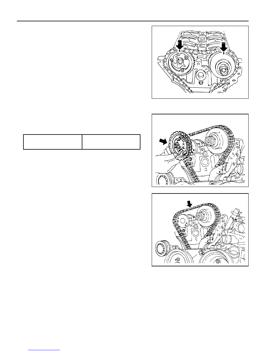
4. Remove the three flange bolts in the exhaust camshaft

sprocket.

Installation Notice

5. Separate the chain from the camshaft sprockrt.

Notice

Be careful not to drop the chain into the timing case.

Do not reuse the removed bolts.

Tools Required

000 589 01 10 00 Box Wrench Insert

116 589 02 34 00

Screw-fixed Pin

116 589 20 33 00

Sliding Hammer

Removal & Installation Procedure

1. Rotate the crankshaft so that the piston of number 1 cylinder

is at TDC.

Notice

Rotate the crankshaft  in the normal engine direction.

2. Put the alignment marks (arrows) on the timing chain and

camshaft sprocket.

3. Drain the coolant from the crankcase.

Tightening Torque

1st step 18 - 22 Nm

2nd step 90° ± 5°

M162 ENGINE MECHANICAL  1B1-37

7. Remove the cylinder head bolts in numerical order.

Installation Notice

8. Check the length of the cylinder head bolt.

Installation Notice

Box  Wrench  Insert   000  589  01  10  00

l

Replace the bolt if the measured length exceed the
max. length.

l

Apply the oil to the thread surface of bolt.

9. Carefully remove the cylinder head and check the mating

surface.

10. Installation should follow the removal procedure in the

reverse order.

6. Remove the guide rail fixing pin from the cylinder head using

the sliding hammer (01) and the threaded pin (02).

Sliding  Hammer  116  589  20  33  00

Threaded  Pin  116  589  02  34  00

Tightening Torque

1st step 55 Nm

2nd step 90°

3rd step 90°

Length (L)

New 160 ± 0.8 mm

Max. 162 ± 0.7 mm

1B1-38  M162 ENGINE MECHANICAL

TIMING GEAR CASE COVER

Preceding Work : Removal of cylinder head front cover

Removal of alternator bracket
Removal of tensioning device
Removal of belt pulley and vibration damper

1 Bolt (M8 x 60, 3 pieces) ................. 22.5-27.5 Nm
2 A/C Bracket
3 Bolt (M8 x 65, 3 pieces) ................. 22.5-27.5 Nm
4 Bolt (M8 x 40, 1 piece) ................... 22.5-27.5 Nm
5 Bolt (M8 x 60, 1 piece) ................... 22.5-27.5 Nm

6 Seal
7 Timing Gear Case Cover
8 Roll Pin
9 Bolt (M6 x 22, 6 pieces) ......................... 9-11 Nm

Removal & Installation Procedure

1. Put the alignment marks (arrows) on the timing chain and

camshaft sprocket.

2. Unscrew the A/C bracket bolts (1) and remove the bracket.

Installation Notice

Tightening  Torque

22.5 - 27.5 Nm

M162 ENGINE MECHANICAL  1B1-39

3. Remove the cooling fan and the viscous clutch. Unscrew

the three bolts from the cooling fan bracket and remove the
bracket (arrows).

Installation Notice

4. Remove the timing gear case cover after unscrewing the

bolts (3) and (4) from the timing gear case cover and the
bolt (9) from the oil pan.

Notice

Be careful not to damage the oil pan gasket.

Installation Notice

l

Apply the sealant after cleaning the timing gear case
cover surface.

l

Be careful not to stain the oil chamber of chain tensioner
with the sealant.

5. Installation should follow the removal procedure in the

reverse order.

6. Warm up the engine and check for oil leaks.

Tightening  Torque

22.5 - 27.5 Nm

Tightening Torque

Bolt (3,4) 22.5 - 27.5 Nm

Bolt (9) 9 - 11 Nm


Content   ..  23  24  25  26   ..