Daewoo Matiz (2003 year). Manual - part 170
5C – 8 CLUTCH
D13C5071
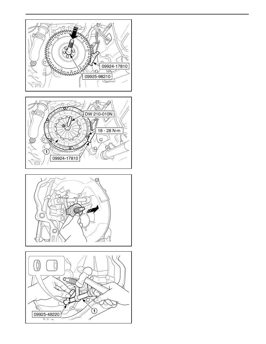
Installation Procedure
1. Install in the reverse order of removal.
2. Install the input shaft bearing using the input shaft
bearing installer 09925–98210 and the flywheel hold-
er 09924–17810.
D13C508B
3. Install the pressure plate and the clutch disc.
D
Install the clutch disc.
D
Install the pressure plate (1).
D
Align the pressure plate and the clutch disc onto the
flywheel using the clutch center guide DW210–010
and the flywheel holder 09924–17810.
D
Install the pressure plate bolts.
Tighten
Tighten the bolts to 18–28 N
S
m (13–21 lb-ft).
D103C510
D103C509
CLUTCH RELEASE BEARING, SHAFT
AND BUSHING
Tools Required
09923–46040
Bushing Joint Pipe
09925–48220
Bushing Remover/Installer
09930–30102
Sliding Shaft
09943–88211
Bushing, Bearing Installer
Removal Procedure
1. Remove the transaxle from the vehicle. Refer to Sec-
tion 5B, Manual Transaxle.
2. Remove the release arm. Refer to “Clutch Release
Arm” in this section.
3. Remove the release bearing.
4. Remove the release shaft and bushing.
D
Remove the bushing (No.2) and seal using the
bushing remover 09925–48220 and hammer.
D
Remove the release shaft (1).