Daewoo Matiz (2003 year). Manual - part 116


  Index      Daewoo     Daewoo Matiz - service repair manual 2003 year


Search            


Content   ..  114  115  116  117   ..


Daewoo Matiz (2003 year). Manual - part 116


REAR SUSPENSION  2D – 5

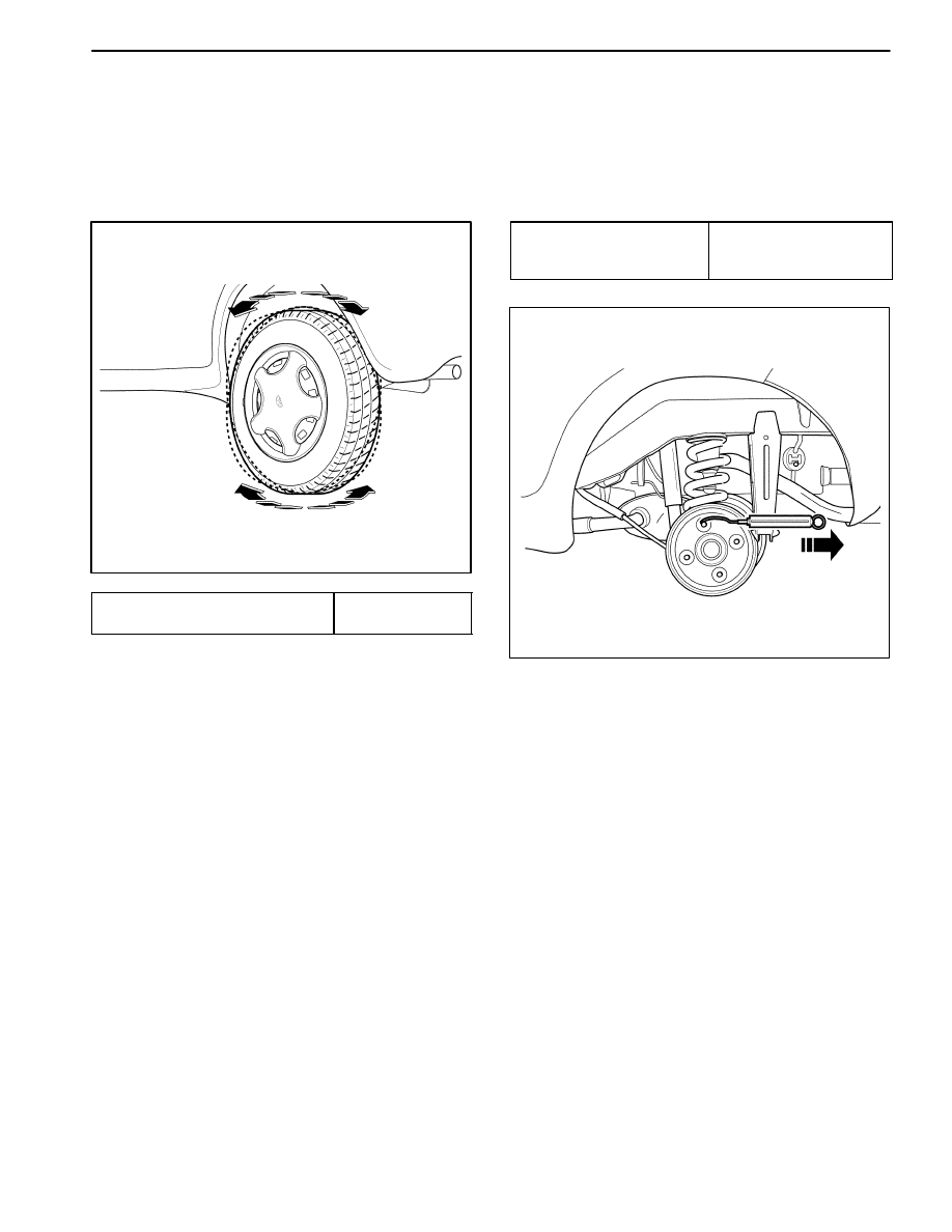
CHECKING THE REAR WHEEL
BEARING END PLAY

1. Release the parking brake.

2. Raise the vehicle.

3. Check the wheel bearing play by moving the top and

the down of the tire in an in–and–out motion.

D106C301

ÁÁÁÁÁÁÁÁÁÁÁ

ÁÁÁÁÁÁÁÁÁÁÁ

ÁÁÁÁÁÁÁÁÁÁÁ

Rear Wheel Bearing Play

ÁÁÁÁÁÁÁ

ÁÁÁÁÁÁÁ

ÁÁÁÁÁÁÁ

0 mm (0 in.)

4. If the bearing play is high, tighten the castellated nut.

5. If the bearing play is high after tightening, replace the

wheel bearing.

REAR WHEEL BEARING FREE LOAD

1. Release the parking brake.

2. Raise the vehicle and rotate the wheel.

3. Remove the wheels.

4. Check the torque when the hub moves by a spring

scale.

ÁÁÁÁÁÁÁÁÁ

ÁÁÁÁÁÁÁÁÁ

ÁÁÁÁÁÁÁÁÁ

Standard (No Load)

ÁÁÁÁÁÁÁÁÁ

ÁÁÁÁÁÁÁÁÁ

ÁÁÁÁÁÁÁÁÁ

0.137 – 0.422 N

S

(0.9 – 3.7 lb-in)

D106C302

5. If the checked torque exceeds the specification, tight-

en the castellated nut.

6. If the checked torque exceeds the specification after

tightening, replace the wheel bearing.

2D – 6  REAR SUSPENSION

REPAIR INSTRUCTIONS

ON–VEHICLE SERVICE

D106C501

SHOCK ABSORBER

Removal Procedure

1. Support the rear axle with adjustable jack stands.

D

Raise the vehicle and support the rear axle assem-
bly (1, 2).

D106C502

2. Remove the shock absorber.

D

Remove the bolt (1).

D

Remove the nut (2).

D16C503B

Installation Procedure

1. Install the shock absorber.

D

Install the shock absorber–to–rear axle bolt (1).

Tighten

Tighten the bolt to 45–70 N

S

m (33–52 lb-ft).

D

Install the shock absorber–to–body bracket nut (2).

Tighten

Tighten the shock absorber nut to 45–70 N

S

m (33–52

lb-ft).

2. Remove the jack stand and lower the vehicle.

REAR SUSPENSION  2D – 7

D106C504

LATERAL ROD

Removal Procedure

1. Raise and suitably support the vehicle.

2. Remove the lateral rod.

D

Remove the lateral rod–to– body bracket bolt (1).

D106C505

D

Remove the lateral rod–to–rear axle nut (2).

D106C506

2. Remove the lateral rod axle side bushing and washer

from the lateral rod.

D16C507A

Installation Procedure

1. Install in the reverse order of removal.

2. Install the lateral rod–to–rear axle side nut.

Tighten

Tighten the lateral rod axle side nut to 35–55 N

S

m

(25–41 lb-ft).

2D – 8  REAR SUSPENSION

D16C508B

3. Install the lateral rod–to–body bracket bolt.

Tighten

Tighten the lateral rod–to–body bracket bolt to 50–70
N

S

m (37–52 lb-ft).

D106C509

TRAILING ARM

Removal Procedure

1. Raise and suitably support the vehicle.

2. Support the rear axle with adjustable jack stands.

3. Separate the rear shock absorber from the rear axle

assembly.

D

Loosen the shock absorber–to–body bracket nut
(1).

D

Remove the shock absorber–to–rear axle bolt (2).

D106C510

4. Remove the trailing arm.

D

Remove the trailing arm–to–rear axle bolts (1).

D106C511

D

Remove the trailing arm–to–body bracket bolt (2).


Content   ..  114  115  116  117   ..