Daewoo Korando. Manual - part 51


  Index      Daewoo     Daewoo Korando - service repair manual


Search            


Content   ..  49  50  51  52   ..


Daewoo Korando. Manual - part 51


1B2-26  M161 ENGINE MECHANICAL
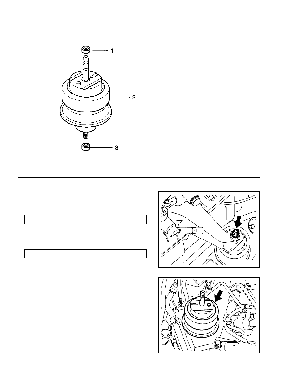
1 Upper Nut
2 Hydraulic Installer ................. 62-93 Nm
3 Lower Nut ............................. 28-47 Nm

Removal and Installation Procedure

1. Unscrew the upper nut(1) on engine mounting and remove

the engine.

Installation Notice

3. Installation should follow the removal procedure in the

reverse order.

Tightening  Torque

62 - 93 Nm

2. Unscrew the lower nut(3) and remove the hydraulic engine

mounting insulator.

Installation Notice

Tightening  Torque

28 - 47 Nm

Notice

If the insulator is spotted with oil, replace the hydraulic
insulator assembly.

M161 ENGINE MECHANICAL  1B2-27

POLY V-BELT

Preceding Work : Removal of cooling fan

1 Poly V-belt (2,155 mm)
2 Belt Tensioning Pulley

Removal & Installation Procedure

1. Release the belt tension by turning the stud on the cap with

12 sided wrench or spanner counterclockwise.

2. Remove the poly v-belt.

Notice

Check the belt for damage and tensioning pulley bearing
point for wear and replace them if necessary.

3. Install the belt after prying the tensioning pulley.

3 Belt Tensioner

1B2-28  M161 ENGINE MECHANICAL

Poly V-belt Arrangement

1 Belt Tensioning Pulley
2 Crankshaft Belt Pulley
3 A/C Compressor Pulley

5 Alternator Pulley
7 Power Steering Pump Pulley
8 Water Pump Pulley

M161 ENGINE MECHANICAL  1B2-29

TENSIONING DEVICE

Preceding Work : Removal of tensioning device shock absorber

1 Bolt (M8 x 75, 2 pieces) +

Washer .......................................... 22.5-27.5 Nm

2 Bolt (M8 x 25, 1 pieces) +

Washer .......................................... 22.5-27.5 Nm

Removal & Installation Procedure

1. Turn the stud bolt to counterclockwise.

2. Insert the pin (111 589 01 15 00) into the hole in tensioning

arm.

3. Unscrew the bolts (1, 2) and remove the tensioning device.

Installation Notice

4. Installation should follow the removal procedure in the

reverse order.

3 Tensioning Device
4 Stud bolt
5 Tensioning Arm

Tightening  Torque

22.5 - 27.5 Nm


Content   ..  49  50  51  52   ..