DAF LF45, LF55 Series. Manual - part 548


  Index      DAF     DAF LF45, LF55 Series - service repair manual


Search            


Content   ..  546  547  548  549   ..


DAF LF45, LF55 Series. Manual - part 548


7

LF45/55 series

Removal and installation

FRONT AXLE, 152N

3-9

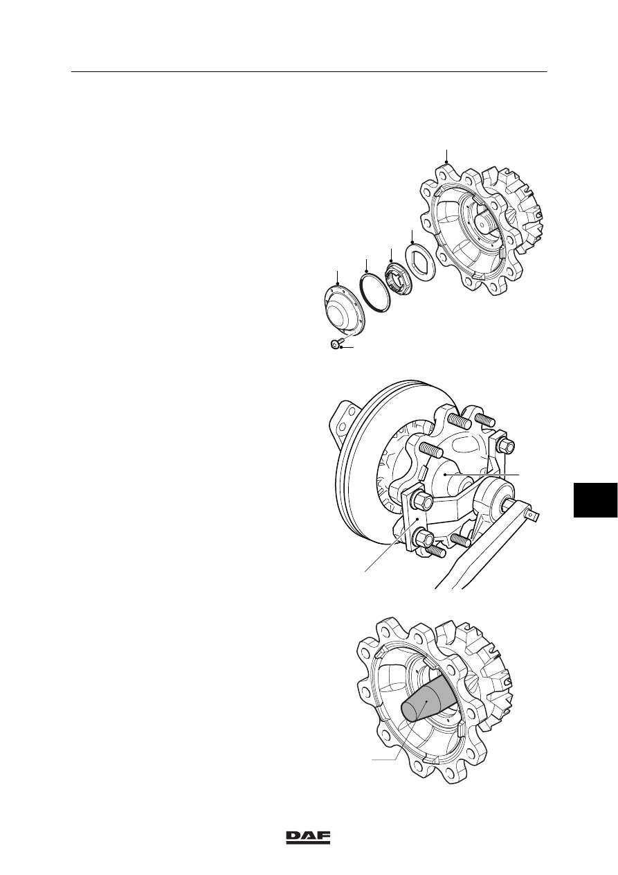
3.5 REMOVAL AND INSTALLATION OF WHEEL HUB UNIT

Removing wheel hub unit
1.

Jack up the axle until the wheels are clear
of the floor. Place suitable supports under
the axle.

2.

Remove the wheel.

3.

Remove the brake calliper.

4.

Remove the hub cover (2).

6

5

2

1

4

3

S7 00 581

5.

Remove the hub nut (4) using the special
tool set (DAF no. 1329496).
Fit the socket wrench (A) to the hub nut. Fit
the socket wrench guide (B) to the wheel
hub unit using four wheel nuts. Loosen the
nut using a torque amplifier.

A

B

S7 00 641

6.

Remove the thrust washer (5).

7.

Fit the guide sleeve (A), which is part of the
special tool set (DAF no. 1329496), to the
axle journal.

8.

Remove the wheel hub unit (6) using a
lifting device. Take care that the wheel hub
unit does not rest on the guide bush (A) as
it is not strong enough to take the weight of
the wheel hub unit.

S7 00 580

A

8

ᓻ 200322

7

FRONT AXLE, 152N

Removal and installation

LF45/55 series

3-10

Installing wheel hub unit
1.

Check the wheel speed sensor ring, see
“Inspection and adjustment”.

2.

Check the axle journal thread carefully for
damage.

The wheel hub unit must never be
fitted to an axle journal with a
damaged thread.

3.

Apply a thin, even layer of the prescribed
anti-corrosion agent to the entire
circumference of the axle journal, see
“Technical data”.

Note:
Do not apply too much anti-corrosion agent to
the axle journal. When the wheel hub unit is
installed, the excess anti-corrosion agent will
collect at the rear of the wheel hub. When the
vehicle is used in daily operation, this can leak
out so that the seal wrongly appears to be
leaking.

S7 00 547

4.

Fit the guide sleeve (A), which is part of the
special tool set (DAF no. 1329496), to the
axle journal.

A

S7 00 561

5.

Check that the spring clip, located between
the inner bearing races, is positioned
correctly.

;;;;;

;;;;;

;;;;;

;;

;;;

;;;

;

;

;;;;;;

;;;

;;;

;;

;

;;

;;

;

;

;;;;;

;;;;;

;;;;;

;;

;;;

;

;;;;;;

;;;;;;

;;;

;;;

;;

;

;;

;;

;

;

S7 00 747

8

ᓻ 200322

7

LF45/55 series

Removal and installation

FRONT AXLE, 152N

3-11

6.

Position the wheel hub unit (6) precisely in
front of the axle journal using a lifting
device. Slide the wheel hub unit (6) onto the
axle journal, without twisting it. Take care
that the wheel hub unit does not rest on the
guide bush (A) as it is not strong enough to
take the weight of the wheel hub unit.

7.

Fit the thrust washer (5).

8.

Replace the hub nut (4). Apply a few drops
of oil to the abutting surface of the hub nut.
Fit the hub nut.

6

5

2

1

4

3

S7 00 581

9.

Fit the hub nut (4) using the special tool set
(DAF no. 1329496).
Fit the socket wrench (A) to the hub nut. Fit
the socket wrench guide (B) to the wheel
hub unit using four wheel nuts. Tighten the
hub nut (4) in the specified manner using a
torque amplifier, see “Technical data”.

10. Fit a new O-ring (3) to the hub cover (2).

11. Fit the brake calliper.

12. Fit the wheel.

A

B

S7 00 641

13. Manually press the wheel speed sensor (2)

against the sensor ring (1). The air gap
between the sensor and the sensor ring is
adjusted while the vehicle is being driven.
If the sensor is stuck, remove, clean and
refit it.

Never tap the sensor with a
hammer. This could damage both
the sensor and the sensor ring.

14. Check the ABS system for correct

operation.

;;;

;;;

;;;

;;;

;;;

;;;;;

;;;;;

;

;

;

;

;;;

;;;

;;

;;

;;

;;

;;

;;

;;

;;

;;

S7 00 543 

2

1

8

ᓻ 200322

7

FRONT AXLE, 152N

Removal and installation

LF45/55 series

3-12

3.6 REMOVAL AND INSTALLATION OF WHEEL-SPEED SENSOR RING

Removing wheel-speed sensor ring
1.

Remove the wheel speed sensor.

2.

Take the wheel hub unit off the axle journal.

3.

Make a notch in the side of the sensor ring,
using a hammer and chisel. Make sure that
the contact surface of the sensor ring to the
wheel hub unit is not damaged in the
process.

4.

Take the sensor ring off the wheel hub unit.

Once removed, the sensor ring
must not be reused.

Installing wheel-speed sensor ring
1.

Check the contact surface of the sensor
ring to the wheel hub unit for damage.

2.

Check the new sensor ring carefully for
possible damage in transit.

3.

Fit a new sensor ring to the wheel hub unit
using a press and flat plate.

4.

Check that the sensor ring makes good
contact around the entire circumference.

5.

Fit the wheel hub unit to the axle journal.

S7 00 554

6.

Manually press the wheel speed sensor (2)
against the sensor ring (1). The air gap
between the sensor and the sensor ring is
adjusted while the vehicle is being driven.
If the sensor is stuck, remove, clean and
refit it.

Never tap the sensor with a
hammer. This could damage both
the sensor and the sensor ring.

7.

Check the ABS system for correct
operation.

;;;

;;;

;;;

;;;

;;;

;;;;;

;;;;;

;

;

;

;

;;;

;;;

;;

;;

;;

;;

;;

;;

;;

;;

;;

S7 00 543 

2

1

8

ᓻ 200322


Content   ..  546  547  548  549   ..