DAF LF45, LF55 Series. Manual - part 525


  Index      DAF     DAF LF45, LF55 Series - service repair manual


Search            


Content   ..  523  524  525  526   ..


DAF LF45, LF55 Series. Manual - part 525


7

LF45/55 series

Removal and installation

FRONT AXLE, F36/F48

3-7

3.5 REMOVAL AND INSTALLATION OF TRACK-ROD ARM

These instructions must be
followed to the letter. The
attachment of the track-rod arms is
one of the most critical factors in
terms of vehicle safety. Always use
new attachment bolts when fitting
the track-rod arm. Always use
original attachment bolts of the
prescribed length supplied by DAF.

Removing track-rod arm

Note:
The track-rod arm and the bottom cover of the
swivel axle form part of a single unit.

1.

Take the track rod off the track-rod arm.
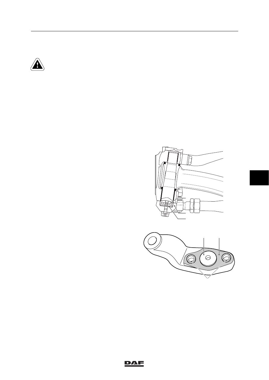
2.

Remove the bottom cover/track-rod
arm (2).

3.

Take the thrust bearing (1) and the
adjusting ring (3) off the bottom cover/track
rod (2).

;

;

;;

;;

;;

;;

;;

;;

;;

;;

;;

;;

;;

;;

;;

;

;

;;

;;

;;

;;

;;

;;

;;

;;

;;

;;

;;

;

;

;

;

S7 00 629

3

2

1

4.

Take the adjusting bushes (4) out of the
bottom cover/track-rod arm (2).

Installing track-rod arm
1.

Fit the adjusting bushes (4) in the bottom
cover/track-rod arm (2).

S7 00 632

4

1

2

6

ᓻ 200322

7

FRONT AXLE, F36/F48

Removal and installation

LF45/55 series

3-8

2.

Check the thrust bearing (1) for wear and
damage. If in doubt, replace the thrust
bearing (1).

3.

Fit the adjusting ring (3).

4.

Fit the thrust bearing (1).

5.

Fit a new O-ring to the bottom of the swivel
axle. Make the O-ring stick by applying a
layer of grease.

6.

Fit the bottom cover/track-rod arm (2).
Tighten the attachment bolts to the
specified tightening torque, see “Technical
data”.

7.

Check the axial swivel axle play, see
“Inspection and adjustment”.

8.

Lubricate the top and bottom bearing when
the vehicle is unloaded until a collar of
grease is visible around the sealing rings.

;

;

;;

;;

;;

;;

;;

;;

;;

;;

;;

;;

;;

;;

;;

;

;

;;

;;

;;

;;

;;

;;

;;

;;

;;

;;

;;

;

;

;

;

S7 00 629

3

2

1

6

ᓻ 200322

7

LF45/55 series

Removal and installation

FRONT AXLE, F36/F48

3-9

3.6 REMOVAL AND INSTALLATION OF HUB

Removing hub
1.

Support the front axle in a safe manner.

2.

Remove the wheel.

3.

Remove the wheel-speed sensor (1).

4.

Reset the brake pads.

5.

Take the brake calliper with attached pipes
off the stub axle. Put the brake calliper to
one side.

1

S7 00 589

6.

Remove the hub cap (11).

7.

Remove the hub nut (10).

8.

Take the hub (5) off the axle end (1). Put
the circlip (8) and the bearing cage (7) to
one side.

9.

Take the oil seal (2) off the hub (5).

10. Take the bearing cage (3) out of the

hub (5).

Installing hub
1.

Clean the axle end (1) and check for
damage.

2.

Clean the bearing cages (3 and 7).

3.

Remove the grease from the hub (5) and
clean the ball races (4 and 6).

4.

Check the bearing cages (3 and 7) and the
ball races (4 and 6) for wear and damage. If
necessary, fit new wheel bearings.

5.

Apply ample quantities of the specified
grease to the bearing cages (3 and 7).

6.

Fit the bearing cage (3) in the hub (5).

1

2

3

4

5

6

7

8

9

10

11

S7 00 573

6

ᓻ 200322

7

FRONT AXLE, F36/F48

Removal and installation

LF45/55 series

3-10

7.

Apply a layer of grease approx. 6 mm thick
to the hub cavity.

;;;;

;;;;

;;;;

;;;;

;;

;;

;;;

;;;;

;;;;

;;;;

;;;;

;;

;;

S7 00 572

8.

Fit a new oil seal (2) in the hub (5).

9.

Fit the lock nut (5) to the axle end (1).

10. Fit the bearing cage (7).

11. Apply the specified grease to the front of

the bearing cage (7).

12. Fit the circlip (8).

13. Fit the hub nut (10). Set the wheel bearing

play, see “Inspection and adjustment”.

14. Fit a new split pin (9).

15. Fit the hub cap (11). Please note: the

hubcap must not be filled with grease.

16. Fit the brake calliper.

17. Set the brake pad clearance. Check that

the brake disc runs freely.

18. Install the wheel speed sensor and press it

against the sensor ring. The required
clearance will be produced while on the
move.

19. Fit the wheel.

1

2

3

4

5

6

7

8

9

10

11

S7 00 573

6

ᓻ 200322


Content   ..  523  524  525  526   ..