DAF LF45, LF55 Series. Manual - part 469
©
200436
3-27
Removal and installation
BRAKE SYSTEM AND COMPONENTS
ΛΦ45/55 series
6
4
3.16 REMOVING AND INSTALLING BELLOWS WITH BRAKE CALLIPER THRUST
PIECE, KNORR SB7000 VERSION
Removing bellows with SB7000 brake calliper
thrust piece
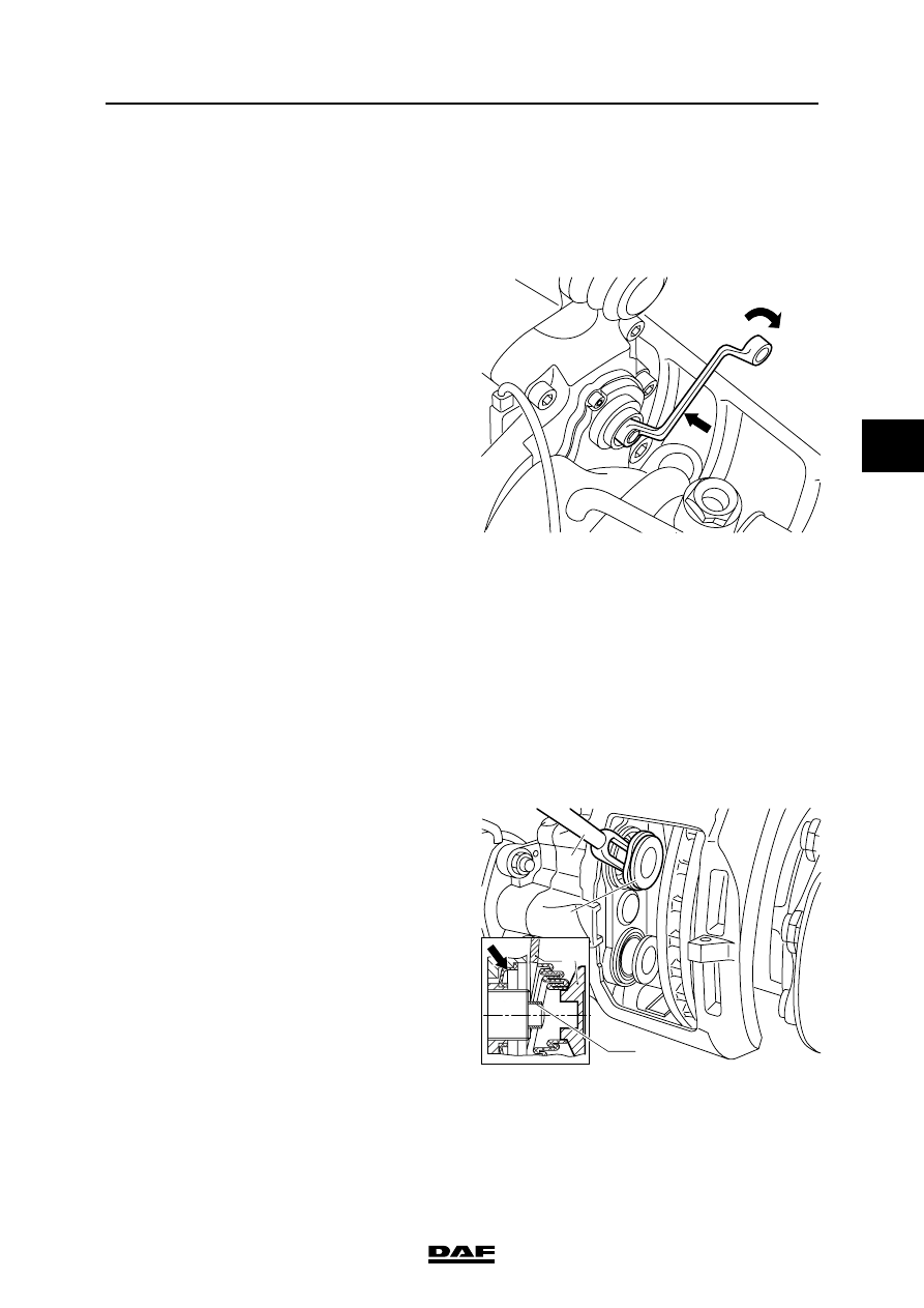
1.
Using the hexagonal adjusting bolt, unscrew
the thrust pieces as far as is necessary to
gain access to the bellows.
Note:
Unscrew the thrust pieces a maximum of
30 mm. Do not screw them completely out of
the brake calliper, as the brake calliper
assembly would then have to be replaced.
Note:
Never turn the hexagonal adjusting bolt
without using an adapter. The adapter is a
torque safety and will break off when the
torque is too high. Without the use of an
adapter the mechanics in the brake calliper
may become damaged when the torque is
too high, so that replacement of the brake
calliper may be necessary.
2.
Using a screwdriver, ease the bellows
behind the thrust piece out of the brake
calliper.
Note:
Do not insert the screwdriver too deeply into
the brake calliper. This could damage the
seat of the inner seal of the thrust pieces.
These cannot be replaced and the brake
calliper would then have to be replaced.
3.
Press the thrust pieces (13) off the adjusters
with the disassembly fork (A), special tool set
(DAF no. 1329494).
4.
Remove the bearing bushes (161) from the
thrust pieces.
R600468
A 13
13
R600469
161
A